S6004DS1RP Littelfuse Inc, S6004DS1RP Datasheet - Page 4
S6004DS1RP
Manufacturer Part Number
S6004DS1RP
Description
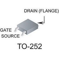
SCR THYRISTOR, 2.5A, 600V, TO-252AA
Manufacturer
Littelfuse Inc
Datasheet
1.S4010LS2.pdf
(12 pages)
Specifications of S6004DS1RP
Peak Repetitive Off-state Voltage, Vdrm
600V
Gate Trigger Current Max, Igt
0.05mA
Current It Av
2.5A
On State Rms Current It(rms)
4A
Peak Non Rep Surge Current Itsm 50hz
25A
Lead Free Status / RoHS Status
Lead free / RoHS Compliant


Sensitive SCRs
Specific Test Conditions
di/dt — Maximum rate-of-change of on-state current; I
dv/dt — Critical rate-of-rise of forward off-state voltage
I
I
I
I
I
I
I
P
P
t
t
V
V
V
V
http://www.littelfuse.com
+1 972-580-7777
2
DRM
GT
GM
H
T
TSM
gt
q
t — RMS surge (non-repetitive) on-state current for period of 8.3 ms
G(AV)
GM
DRM
GRM
GT
TM
— Maximum on-state current
— DC holding current; initial on-state current = 20 mA
— Circuit commutated turn-off time
— Gate controlled turn-on time gate pulse = 10 mA; minimum
TYPE
— DC gate trigger current V
— Peak gate current
10 A
width ≥15 µsec with ≤0.1 µs rise time
for fusing
width = 15 µS with rise time ≤0.1 µs
— DC gate trigger voltage; V
— Peak on-state voltage
6 A
8 A
— Peak one-cycle forward surge current
— Peak gate power dissipation
and I
and V
— Peak reverse gate voltage
— Average gate power dissipation
RRM
RRM
— Peak off-state current at V
— Repetitive peak off-state forward and reverse voltage
S2006LS2
S4006LS2
S6006LS2
S2006LS3
S4006LS3
S6006LS3
S2008LS2
S4008LS2
S6008LS2
S2008LS3
S4008LS3
S6008LS3
S2010LS2
S4010LS2
S6010LS2
S2010LS3
S4010LS3
S6010LS3
Isolated
K
TO-220
A
See “Package Dimensions” section for variations. (11)
G
D
D
= 6 V dc; R
S2006FS21
S4006FS21
S6006FS21
S2006FS31
S4006FS31
S6006FS31
S2008FS21
S4008FS21
S6008FS21
S2008FS31
S4008FS31
S6008FS31
S2010FS21
S4010FS21
S6010FS21
S2010FS31
S4010FS31
S6010FS31
K
= 6 V dc; R
TO-202
A
Part Number
G
A
DRM
L
= 100 Ω
L
and V
= 100 Ω
Non-isolated
S2006VS2
S4006VS2
S6006VS2
S2006VS3
S4006VS3
S6006VS3
S2008VS2
S4008VS2
S6008VS2
S2008VS3
S4008VS3
S6008VS3
S2010VS2
S4010VS2
S6010VS2
S2010VS3
S4010VS3
S6010VS3
K
TO-251
V-Pak
A
RRM
GT
A
= 50 mA pulse
G
A
S2006DS2
S4006DS2
S6006DS2
S2006DS3
S4006DS3
S6006DS3
S2008DS2
S4008DS2
S6008DS2
S2008DS3
S4008DS3
S6008DS3
S2010DS2
S4010DS2
S6010DS2
S2010DS3
S4010DS3
S6010DS3
TO-252
D-Pak
E5 - 4
K
A
G
General Notes
•
•
•
•
•
•
•
I
T(RMS)
MAX
Teccor 2N5064 and 2N6565 Series devices conform to all JEDEC
registered data. See specifications table on pages E5 - 2 and
E5 - 3.
The case lead temperature (
dimensional outline drawings in the “Package Dimensions” section
of this catalog.
All measurements (except I
R
All measurements are made at 60 Hz with a resistive load at an
ambient temperature of +25 °C unless otherwise specified.
Operating temperature (T
devices, -65 °C to +125 °C for 2N Series devices, -40 °C to
+125 °C for “TCR” Series, and -40 °C to +110 °C for all others.
Storage temperature range (T
devices, -40 °C to +150 °C for TO-202 and Compak devices, and
-40 °C to +125 °C for all others.
Lead solder temperature is a maximum of +230 °C for 10 seconds
maximum ≥1/16" (1.59 mm) from case.
10
10
10
10
10
10
6
6
6
6
6
6
8
8
8
8
8
8
GK
Amps
= 1 kΩ unless otherwise noted.
(1)
I
T
I
MAX
T(AV)
3.8
3.8
3.8
3.8
3.8
3.8
5.1
5.1
5.1
5.1
5.1
5.1
6.4
6.4
6.4
6.4
6.4
6.4
V
V
DRM
Volts
MIN
200
400
600
200
400
600
200
400
600
200
400
600
200
400
600
200
400
600
RRM
&
J
) is -65 °C to +110 °C for EC Series
GT
T
) are made with an external resistor
C
S
) is -65 °C to +150 °C for TO-92
or T
(2) (12)
µAmps
MAX
200
200
200
500
500
500
200
200
200
500
500
500
200
200
200
500
500
500
I
GT
L
) is measured as shown on
Thyristor Product Catalog
25 °C
MAX
T
C
5
5
5
5
5
5
5
5
5
5
5
5
5
5
5
5
5
5
(20) (21)
©2004 Littelfuse, Inc.
I
µAmps
=
DRM
I
RRM
110 °C
&
MAX
T
250
250
250
250
250
250
250
250
250
250
250
250
250
250
250
250
250
250
C
=
Data Sheets
(3) (10)
V
Volts
MAX
1.6
1.6
1.6
1.6
1.6
1.6
1.6
1.6
1.6
1.6
1.6
1.6
1.6
1.6
1.6
1.6
1.6
1.6
TM
Related parts for S6004DS1RP
Image
Part Number
Description
Manufacturer
Datasheet
Request
R


Part Number:
Description:
Conn Relay Socket Skt 20 Pos St Panel Mount
Manufacturer:
ETC-unknow
Datasheet:

Part Number:
Description:
FUSEHOLDER 20A MINI INLINE CRIMP
Manufacturer:
Littelfuse Inc
Datasheet:

Part Number:
Description:
FUSEHOLDER BODY ATO INLINE PNLMT
Manufacturer:
Littelfuse Inc
Datasheet:

Part Number:
Description:
FUSE 2A 63V FAST 1206
Manufacturer:
Littelfuse Inc
Datasheet:
Part Number:
Description:
FUSE 1.25A 63V FAST 1206
Manufacturer:
Littelfuse Inc
Datasheet:
Part Number:
Description:
FUSE .250A 125V FAST 1206
Manufacturer:
Littelfuse Inc
Datasheet:
Part Number:
Description:
FUSE 4A 32V FAST 1206
Manufacturer:
Littelfuse Inc
Datasheet:
Part Number:
Description:
FUSE 1.75A 63V FAST 1206
Manufacturer:
Littelfuse Inc
Datasheet:

Part Number:
Description:
FUSE 1A 32V FST 0603 LEADFREE TR
Manufacturer:
Littelfuse Inc
Datasheet:

Part Number:
Description:
FUSE 1A 32V FAST SLIM 0402
Manufacturer:
Littelfuse Inc
Datasheet:

Part Number:
Description:
FUSE 2A 125V FAST NANO2 SMD
Manufacturer:
Littelfuse Inc
Datasheet:

Part Number:
Description:
FUSE .250A 125V FAST NANO2 SMD
Manufacturer:
Littelfuse Inc
Datasheet:

Part Number:
Description:
FUSE .500A 125V FAST NANO2 SMD
Manufacturer:
Littelfuse Inc
Datasheet: