S6010DRP Littelfuse Inc, S6010DRP Datasheet - Page 11
S6010DRP
Manufacturer Part Number
S6010DRP
Description
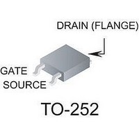
SCR THYRISTOR, 6.4A, 600V, TO-252AA
Manufacturer
Littelfuse Inc
Datasheet
1.S2006DRP.pdf
(12 pages)
Specifications of S6010DRP
Peak Repetitive Off-state Voltage, Vdrm
600V
Gate Trigger Current Max, Igt
15mA
Current It Av
6.4A
On State Rms Current It(rms)
10A
Peak Non Rep Surge Current Itsm 50hz
83A
Lead Free Status / RoHS Status
Lead free / RoHS Compliant


Data Sheets
Figure E6.23 Peak Surge Current versus Surge Current Duration
Figure E6.24 Power Dissipation (Typical) versus RMS On-state Current
©2004 Littelfuse, Inc.
Thyristor Product Catalog
(1 A)
0.6
1.0
0.8
0.4
0.2
0
RMS On-state Current [I
0
CURRENT WAVEFORM: Half Sine Wave
LOAD: Resistive or Inductive
CONDUCTION ANGLE: 180˚
0.2
1000
100
200
800
600
500
400
300
80
60
40
30
20
10
50
8
4
6
5
2
3
1.0 A Devices
1
0.4
1
Notes:
1) Gate control may be lost during and
2) Overload may not be repeated until
0.6
steady-state rated value.
immediately following surge current
interval.
junction temperature has returned to
2
0.8
T(RMS)
3
1.0
] – Amps
4
5
Surge Current Duration – Full Cycles
6 7 8 10
E6 - 11
20 30 40 60 80100
Figure E6.25 Power Dissipation (Typical) versus RMS On-state Current
SUPPLY FREQUENCY: 60 Hz Sinusoidal
LOAD: Resistive
RMS ON-STATE CURRENT: [I T(RMS) ]: Max-
Rated Value at Specified Case Temperature
(6 A through 20 A)
18
16
14
12
10
8
6
4
2
0
0
CURRENT WAVEFORM: Half Sine Wave
LOAD: Resistive or Inductive
CONDUCTION ANGLE: 180˚
2
200 300400 600 1000
RMS On-state Current [I
4
6 A to 10 A Devices
6
12 A Devices
8
15 A to 20 A Devices
10
12
T(RMS)
http://www.littelfuse.com
14
] – Amps
16
+1 972-580-7777
18
20
SCRs
Related parts for S6010DRP
Image
Part Number
Description
Manufacturer
Datasheet
Request
R

Part Number:
Description:
FUSEHOLDER 20A MINI INLINE CRIMP
Manufacturer:
Littelfuse Inc
Datasheet:

Part Number:
Description:
FUSEHOLDER BODY ATO INLINE PNLMT
Manufacturer:
Littelfuse Inc
Datasheet:

Part Number:
Description:
FUSE 2A 63V FAST 1206
Manufacturer:
Littelfuse Inc
Datasheet:
Part Number:
Description:
FUSE 1.25A 63V FAST 1206
Manufacturer:
Littelfuse Inc
Datasheet:
Part Number:
Description:
FUSE .250A 125V FAST 1206
Manufacturer:
Littelfuse Inc
Datasheet:
Part Number:
Description:
FUSE 4A 32V FAST 1206
Manufacturer:
Littelfuse Inc
Datasheet:
Part Number:
Description:
FUSE 1.75A 63V FAST 1206
Manufacturer:
Littelfuse Inc
Datasheet:

Part Number:
Description:
FUSE 1A 32V FST 0603 LEADFREE TR
Manufacturer:
Littelfuse Inc
Datasheet:

Part Number:
Description:
FUSE 1A 32V FAST SLIM 0402
Manufacturer:
Littelfuse Inc
Datasheet:

Part Number:
Description:
FUSE 2A 125V FAST NANO2 SMD
Manufacturer:
Littelfuse Inc
Datasheet:

Part Number:
Description:
FUSE .250A 125V FAST NANO2 SMD
Manufacturer:
Littelfuse Inc
Datasheet:

Part Number:
Description:
FUSE .500A 125V FAST NANO2 SMD
Manufacturer:
Littelfuse Inc
Datasheet:

Part Number:
Description:
FUSE 1.5A 125V FAST NANO2 SMD
Manufacturer:
Littelfuse Inc
Datasheet:

Part Number:
Description:
FUSE 4A 125V FAST NANO2 SMD
Manufacturer:
Littelfuse Inc
Datasheet:

Part Number:
Description:
FUSE 1A 125V FAST NANO2 SMD
Manufacturer:
Littelfuse Inc
Datasheet: