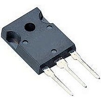
TIP146 MULTICOMP, TIP146 Datasheet - Page 4

TIP146
Manufacturer Part Number
TIP146
Description
DARLINGTON TRANSISTOR, PNP, -80V
Manufacturer
MULTICOMP
Datasheet
1.TIP141.pdf
(7 pages)
Specifications of TIP146
Transistor Polarity
PNP
Collector Emitter Voltage V(br)ceo
80V
Power Dissipation Pd
125W
Dc Collector Current
-10A
Dc Current Gain Hfe
1000
Operating Temperature Range
-65°C To +150°C
Lead Free Status / RoHS Status
Lead free / RoHS Compliant
Available stocks
Company
Part Number
Manufacturer
Quantity
Price
Company:
Part Number:
TIP146
Manufacturer:
NEC
Quantity:
10 000
Part Number:
TIP146
Manufacturer:
ST
Quantity:
20 000
Part Number:
TIP146T
Manufacturer:
ST
Quantity:
20 000
Internal Schematic Diagram
NPN : TIP140, TIP141, TIP142
Active Region Safe Operating Area (SOA)
TIP140 to TIP142 & TIP145 to TIP147
Darlington Transistors
Small-Signal Common-Emitter Forward Current
Transfer Ratio
There are two limitations on the power handling ability of a transistor:
average junction temperature and second breakdown safe operating
area curves indicate I
observed for reliable operation i.e., the transistor must not be subjected
to greater dissipation than curves indicate.
The data of SOA curve is base on T
depending on conditions. At high case temperatures, thermal limitation
will reduce the power that can be handled to values less than the
limitations imposed by second breakdown.
Page 4
PNP : TIP145, TIP146, TIP147
Unclamped Inductive Load
C
-V
CE
limits of the transistor that must be
J (PK)
= 150°C; T
C
is variable
04/04/05 V1.0


