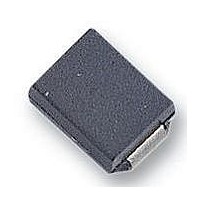
VS-10BQ040TRPBF Vishay, VS-10BQ040TRPBF Datasheet

VS-10BQ040TRPBF
Specifications of VS-10BQ040TRPBF
Available stocks
Related parts for VS-10BQ040TRPBF
VS-10BQ040TRPBF Summary of contents
Page 1
SCHOTTKY RECTIFIER Major Ratings and Characteristics Characteristics 10BQ040 I Rectangular waveform 1.0 F(AV RRM µs sine 430 FSM V @ 1.0 Apk, T =125°C 0. range - 55 to 150 ...
Page 2
Bulletin PD-2.397 rev. G 07/04 Voltage Ratings Part number V Max. DC Reverse Voltage ( Max. Working Peak Reverse Voltage (V) RWM Absolute Maximum Ratings Parameters I Max. Average Forward Current F(AV) I Max. Peak One Cycle ...
Page 3
... Rectangular Pulse Duration (Seconds) 1 Characteristics (Per Leg) thJC 10BQ040 Bulletin PD-2.397 rev. G 07/ 150˚C 125˚C 100˚C 75˚C 50˚C 25˚ Reverse Voltage - V (V) R Fig Typical Peak Reverse Current Vs. Reverse Voltage T = 25˚ Reverse Voltage - V (V) R Fig Typical Junction Capacitance Vs. Reverse Voltage 100 3 ...
Page 4
... Average Forward Current - I Fig Maximum Average Forward Current Vs. Allowable Lead Temperature 1000 100 10 10 Square Wave Pulse Duration - T Fig Maximum Peak Surge Forward Current Vs. Pulse Duration (2) Formula used ( REV Pd = Forward Power Loss = F(AV Inverse Power Loss = ...
Page 5
Outline Table Device Marking: IR1F 2.15 (.085) 1.80 (.071) 4.70 (.185) 4.10 (.161) 2.40 (.094) 1.90 (.075) 1.30 (.051) 0.76 (.030) 5.60 (.220) 5.00 (.197) For recommended footprint and soldering techniques refer to application note #AN-994 Marking & Identification Each ...
Page 6
Bulletin PD-2.397 rev. G 07/04 Tape & Reel Information Dimensions in millimetres and (inches) Ordering Information Table Device Code WORLD HEADQUARTERS: 233 Kansas St., El Segundo, California 90245, USA Tel: (310) 252-7105 ...


