09-48-3044 Molex Inc, 09-48-3044 Datasheet

CONN RECEPT 4POS .156 VERT PCB

09-48-3044

Manufacturer Part Number
09-48-3044
Description
CONN RECEPT 4POS .156 VERT PCB
Manufacturer
Molex Inc
Series
KK® 41815r
Datasheets

Specifications of 09-48-3044

Connector Type
Receptacle, Bottom Entry
Contact Type
Female Socket
Number Of Positions
4
Number Of Positions Loaded
All
Pitch
0.156" (3.96mm)
Number Of Rows
1
Mounting Type
Through Hole
Termination
Solder
Fastening Type
Ramp
Contact Finish
Gold
Contact Finish Thickness
15µin (0.38µm)
Color
Natural
Pitch Spacing
3.96mm
No. Of Rows
1
No. Of Contacts
4
Gender
Receptacle
Contact Termination
Through Hole
Contact Plating
Gold
Contact Material
Brass
Product Type
Receptacles / Sockets - PCB
Number Of Positions / Contacts
4
Mounting Style
Through Hole
Termination Style
Solder
Housing Material
Polyester
Voltage Rating
250 V
Current Rating
5 A
Lead Free Status / RoHS Status
Lead free / RoHS Compliant
Features
-
Row Spacing
-
Lead Free Status / Rohs Status
 Details
Other names
0009-48-3044
0009-48-3044-E
0009483044
0009483044-E
09-48-3044-E
09483044
09483044-E
WM13521

Available stocks

Company
Part Number
Manufacturer
Quantity
Price
Part Number:
09-48-3044
Manufacturer:
Molex Connector Corporation
Quantity:
231
REVISION:
DOCUMENT NUMBER:
1.0 SCOPE
2.0 PRODUCT DESCRIPTION
3.0 APPLICABLE DOCUMENTS AND SPECIFICATIONS
4.0 RATINGS
R3
This Product Specification covers the 3.96 mm (.156 inch) centerline (pitch) 1.14mm (.045) square
pin headers when mated with either printed circuit board (PCB) connectors or connectors terminated
with 18 to 26 AWG wire using crimp technology.
2.1 PRODUCT NAME AND SERIES NUMBERS
2.2 DIMENSIONS, MATERIALS, PLATINGS AND MARKINGS
2.3 SAFETY AGENCY APPROVALS
3.1 PS-45499-002
4.1 VOLTAGE
4.2 CURRENT (Current is dependent on connector size, contact material, plating, ambient
Crimp Terminals: 2478,2578,2878,2477,
Crimp Housings: 2139, 41695
PCB Connectors: 2145, 41815
Headers: 41771, 41772, 41791, 41792, 42471, 42472, 42491, 42492, 41661, 41662, 41671,
61672, 41681, 41682
Other products conforming to this specification are noted on the individual drawings.
a. For Crimp Terminals- and Applicable Wires
For more information on dimensions, materials, and plating see the individual drawings.
Terminal Material: Brass or Phos. Bronze (for Max performance use phos bronze material.)
Housing: Nylon or Polyester
Pins: Brass or Phos. Bronze
UL File Number …….. E29179
CSA ………………......LR19980
250 Volts
temperature, printed circuit board characteristics and related factors. Actual current rating is
application dependent and should be evaluated for each application.)
Wire
Awg
PS-08-50
18
20
22
24
26
ECR/ECN INFORMATION:
EC No:
DATE:
UCP2008-1760
2008/01/30
Amps (Max)
With Brass
5.00
4.75
4.50
4.25
4.00
COSMETIC SPECIFICATION
PRODUCT SPECIFICATION
Amps (Max)
With Phos Bronze
TITLE:
CREATED / REVISED BY:
7.00
6.25
5.50
5.00
4.50
ADERR
.156 CENTER KK CONNECTORS
PRODUCT SPECIFICATION
Wire Insulation Dia
See terminal drawings
CHECKED BY:
JBELL
TEMPLATE FILENAME: PRODUCT_SPEC[SIZE_A](V.1).DOC
APPROVED BY:
FSMITH
SHEET No.
1
of
5

Related parts for 09-48-3044

09-48-3044 Summary of contents

Page 1

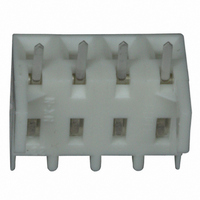
SCOPE This Product Specification covers the 3.96 mm (.156 inch) centerline (pitch) 1.14mm (.045) square pin headers when mated with either printed circuit board (PCB) connectors or connectors terminated with AWG wire using crimp technology. 2.0 ...

Page 2

CURRENT (cont) b. For Printed Circuit Board Connectors Connector Amps (Max) Style With Brass Top Entry Right Angle Bottom Entry 4.3 TEMPERATURE (ambient + 30 Operating Temperature Non Operating Temperature 5.0 PERFORMANCE 5.1 ELECTRICAL REQUIREMENTS DESCRIPTION TEST CONDITION Contact ...

Page 3

MECHANICAL REQUIREMENTS DESCRIPTION TEST CONDITION Per circuit when mated to a .045 Sq. pin. Connector Mate Mate and unmate connector (male to female) and at a rate of 25 ± ± ¼ inch) per Unmate Forces ...

Page 4

ENVIRONMENTAL REQUIREMENTS DESCRIPTION TEST CONDITION Mate connectors; expose to 5 cycles of: Temperature ° C Shock -40 +0/-3 (Thermal) +25 ±10 +105 +3/-0 +25 ±10 Mate connectors; expose to: Thermal Aging 96 hours at 105 ± 2° C Mate ...

Page 5

ENVIRONMENTAL REQUIREMENTS DESCRIPTION TEST CONDITION Dip connector terminal tails in solder: Solder Solder Duration: 5 ± 0.5 seconds; Resistance Solder Temperature: 230 ± 5° C Mate connectors: Cold Resistance Duration: 96 hours; Temperature: -40 ± 3° C Corrosive Atmosphere: ...

Related keywords