8AF4RPP Vishay, 8AF4RPP Datasheet - Page 2
8AF4RPP
Manufacturer Part Number
8AF4RPP
Description
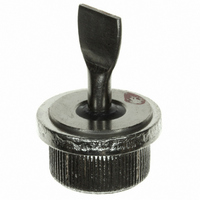
RECTIFIER DIODE,400V V(RRM),PRESS-13
Manufacturer
Vishay
Datasheet
1.8AF1RPP.pdf
(6 pages)
Specifications of 8AF4RPP
Rohs Compliant
YES
Voltage - Dc Reverse (vr) (max)
400V
Current - Average Rectified (io)
50A
Current - Reverse Leakage @ Vr
5mA @ 400V
Diode Type
Standard
Speed
Standard Recovery >500ns, > 200mA (Io)
Mounting Type
Chassis, Stud Mount
Package / Case
B-47
Product
Standard Recovery Rectifier
Configuration
Single
Reverse Voltage
400 V
Forward Voltage Drop
1.45 V
Forward Continuous Current
50 A
Max Surge Current
747 A
Reverse Current Ir
5000 uA
Mounting Style
Stud
Maximum Operating Temperature
+ 195 C
Minimum Operating Temperature
- 65 C
Lead Free Status / RoHS Status
Lead free / RoHS Compliant
Reverse Recovery Time (trr)
-
Voltage - Forward (vf) (max) @ If
-
Capacitance @ Vr, F
-
Lead Free Status / RoHS Status
Lead free / RoHS Compliant
Other names
*8AF4RPP
VS-8AF4RPP
VS-8AF4RPP
VS8AF4RPP
VS8AF4RPP
VS-8AF4RPP
VS-8AF4RPP
VS8AF4RPP
VS8AF4RPP


8AF Series
Vishay High Power Products
Note
(1)
www.vishay.com
2
FORWARD CONDUCTION
PARAMETER
Maximum average forward current
at case temperature
Maximum RMS forward current
Maximum peak, one cycle forward,
non-repetitive surge current
Maximum I
Maximum I
Low level value of threshold voltage
High level value of threshold voltage
Low level value of forward slope resistance
High level value of forward slope resistance
Maximum forward voltage drop
THERMAL AND MECHANICAL SPECIFICATIONS
PARAMETER
Maximum junction operating
and storage temperature range
Maximum thermal resistance,
junction to case
Typical thermal resistance,
case to heatsink
Approximate weight
Case style
Mounting: A 12.6 ± 0.02 mm (0.496 to 0.497") diameter hole should be drilled in heatsink, the leading edge chamfered to 0.038 mm
(0.015") x 45°. The autodiode should then be press fitted, ensuring that the sides of the autodiode are kept parallel to the sides of the hole.
2
2
t for fusing
√t for fusing
SYMBOL
T
R
R
J
, T
thCS
thJC
For technical questions, contact: ind-modules@vishay.com
Stg
SYMBOL
V
V
I
I
F(RMS)
I
F(AV)
F(TO)1
F(TO)2
V
I
FSM
I
2
r
r
Pressfit Rectifier Diodes, 50 A
2
f1
f2
FM
DC operation
As per mounting details, see note
See dimensions - link at the end of datasheet
√t
t
180° conduction, half sine wave
t = 10 ms
t = 8.3 ms
t = 10 ms
t = 8.3 ms
t = 10 ms
t = 8.3 ms
t = 10 ms
t = 8.3 ms
t = 0.1 to 10 ms, no voltage reapplied
(16.7 % x π x I
(π x I
(16.7 % x π x I
(π x I
T
J
= 25 °C, I
TEST CONDITIONS
F(AV)
F(AV)
< I < 20 x π x I
< I < 20 x π x I
FM
F(AV)
F(AV)
= π x rated I
No voltage
reapplied
100 % V
reapplied
No voltage
reapplied
100 % V
reapplied
TEST CONDITIONS
< I < π x I
< I < π x I
F(AV)
F(AV)
RRM
RRM
(1)
F(AV)
F(AV)
), T
F(AV)
), T
J
J
), T
), T
= T
= T
Sinusoidal half wave,
initial T
T
J
J
J
J
J
= T
= T
maximum
maximum
maximum
J
J
J
maximum
maximum
- 65 to 195
VALUES
=
0.60
0.50
0.36
10
Document Number: 93530
B-47
VALUES
25 455
2546
2324
1800
1643
0.60
0.68
6.66
6.25
1.45
150
714
747
600
628
Revision: 17-Jun-08
50
79
UNITS
K/W
oz.
°C
g
UNITS
A
A
mΩ
°C
2
A
A
A
V
V
2
√s
s
Related parts for 8AF4RPP
Image
Part Number
Description
Manufacturer
Datasheet
Request
R

Part Number:
Description:
8A, 100V Bridge Rectifier, GBU / BULK (TUBE)
Manufacturer:
Micro Commercial Components (MCC)
Datasheet:

Part Number:
Description:
8A, 600V Bridge Rectifier, GBU / BULK (TUBE)
Manufacturer:
Micro Commercial Components (MCC)
Datasheet:

Part Number:
Description:
8A,50V,GPP,PLASTIC RECT
Manufacturer:
Vishay
Datasheet:
Part Number:
Description:
8A,100V,GPP,PLASTIC RECT
Manufacturer:
Vishay
Datasheet:
Part Number:
Description:
8A,200V,GPP,PLASTIC RECT
Manufacturer:
Vishay
Datasheet:
Part Number:
Description:
8A,400V,GPP,PLASTIC RECT
Manufacturer:
Vishay
Datasheet:
Part Number:
Description:
8A,800V,GPP,PLASTIC RECT
Manufacturer:
Vishay
Datasheet:
Part Number:
Description:
8A,1000V,GPP,PLASTIC RECT
Manufacturer:
Vishay
Datasheet:

Part Number:
Description:
8A,30V,SM SKY RECT.
Manufacturer:
Vishay
Datasheet:

Part Number:
Description:
8A,200V,25NS,SINGLE UF RECT
Manufacturer:
Vishay
Datasheet:
Part Number:
Description:
8A, 50V Bridge Rectifier, GBU / BULK (TUBE)
Manufacturer:
Micro Commercial Components (MCC)
Datasheet:
Part Number:
Description:
8A, 200V Bridge Rectifier, GBU / BULK (TUBE)
Manufacturer:
Micro Commercial Components (MCC)
Datasheet:
Part Number:
Description:
8A, 400V Bridge Rectifier, GBU / BULK (TUBE)
Manufacturer:
Micro Commercial Components (MCC)
Datasheet:

Part Number:
Description:
8A,600V,GPP,INLINE BRIDGE
Manufacturer:
Vishay
Datasheet:
Part Number:
Description:
8A, 80V Bridge Rectifier, GBU / BULK (TUBE)
Manufacturer:
Micro Commercial Components (MCC)
Datasheet: