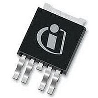
AUIPS7221R International Rectifier, AUIPS7221R Datasheet

AUIPS7221R
Specifications of AUIPS7221R
Available stocks
Related parts for AUIPS7221R
AUIPS7221R Summary of contents
Page 1
... Typical Connection 4k7 4k7 Input Signal V Diag www.irf.com o feedback. An integrated +Bat In(1) Control Gnd(2) Automotive grade AUIPS7221R Product Summary Rds(on) 35m max. Vbr 75V min. I shutdown 25A(min.) Package D-Pak Vcc(3) Cb(4) Bootstrap capacitor Out(5) *Required, see absolute ...
Page 2
... Exceptions to AEC-Q100 requirements are noted in the qualification report. www.irf.com † Comments: This family of ICs has passed an Automotive qualification. IR’s Industrial and Consumer qualification level is granted by extension of the higher Automotive level. DPAK-5L AUIPS7221R Automotive †† (per AEC-Q100 ) MSL1, 260°C (per IPC/JEDEC J-STD-020) ...
Page 3
... Recommended resistor in series with IN pin Rdg Recommended resistor in series with dg pin F max. Max. switching frequency Cboot Bootstrap capacitor (1) limited by the maximum input current (2) limited by the input capacitor www.irf.com Rth=50°C/W 1”sqrt. footprint AUIPS7221R Min. Max. Units Gnd-3 Vcc+0.3 Vcc-65 Vcc+0.3 V -0.3 5.5 65 ...
Page 4
... AUIPS7221R Test Conditions Vin=5V, Iout=5A Vin=5V, Iout=5A During sleep mode Vin=0V, Vout=0V Tj=25°C, Vcc=28V Vin=5V Tj=25°C, Vcc=28V Vin=0V Tj=25°C, Vcc=28V Vin=5V I in=5mA Test Conditions Test Conditions Vout=0V see figure 1 see figure 2 ...
Page 5
... Lead Assignments Functional Block Diagram All values are typical 2V 1.5V 75V Sleep 350k 6V Gnd IN www.irf.com 3- Vcc Gnd 3- Vcc Out Pak Under Voltage diag Iout>30A Tj > 165°C AUIPS7221R Vcc Bootstrap regulator Level Driver Shifter Charge Pump OUT Cboot 75V 6V 5 ...
Page 6
... To wake up the part from the sleep mode, the input must be activated at least during Twkp, then the boostrap regulator is switched on and the boostrap capacitor is charged. The output will be not activated during Tpw on rst. www.irf.com Tdiag Tsleep Tdiag Fault mode Cboot Out Load AUIPS7221R Treset sleep mode 6 ...
Page 7
... IN Tpw on rst out Twkp sleep mode Figure 2 IN Tpw on rst out Twkp sleep mode Figure 3 www.irf.com Tsleep Normal mode Normal mode AUIPS7221R sleep mode 7 ...
Page 8
... Tj, junction temperature (°C) Figure 5 - Normalized Rds(on) (%) Vs Tj (°C) 0.5 0.4 0.3 0.2 0.1 0.0 -50 0 Tj, junction temperature (°C) Figure 7 – (µ (°C) www.irf.com 50 100 150 100 150 AUIPS7221R - Tj, junction temperature (°C) Figure 6 – Isd ( (°C) 2.0 1.5 1.0 tdon 0.5 tdoff 0.0 - 100 Tj, junction temperature (° ...
Page 9
... Figure 9 – Transient thermal impedance (°C/W) Vs time (s) 0.20 0.15 0.10 0.05 0. Vcc, supply voltage (V) Figure 11 – Icc off(A) Vs Vcc (V) www.irf.com 1 e-1 1 e+0 1 e+1 1 e+2 1 e+3 Time ( AUIPS7221R - Tj, junction temperature (°C) Figure 10 – Icc off (µ (°C) 100 150 9 ...
Page 10
... Case Outline 5 Lead – DPAK www.irf.com AUIPS7221R 10 ...
Page 11
... Tape & Reel 5 Lead – DPAK www.irf.com AUIPS7221R 11 ...
Page 12
... Part Marking Information Ordering Information Base Part Number Package Type AUIPS7221R D-Pak-5-Lead www.irf.com Standard Pack Form Tube Tape and reel Tape and reel left Tape and reel right AUIPS7221R Complete Part Number Quantity 75 AUIPS7221R 2000 AUIPS7221RTR 3000 AUIPS7221RTRL 3000 AUIPS7221RTRR 12 ...
Page 13
... Buyers acknowledge and agree that, if they use any non-designated products in automotive applications, IR will not be responsible for any failure to meet such requirements. For technical support, please contact IR’s Technical Assistance Center www.irf.com IMPORTANT NOTICE http://www.irf.com/technical-info/ WORLD HEADQUARTERS: 233 Kansas St., El Segundo, California 90245 Tel: (310) 252-7105 AUIPS7221R 13 ...


