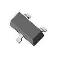
AZ23C24-V-GS08 Vishay, AZ23C24-V-GS08 Datasheet - Page 5

AZ23C24-V-GS08
Manufacturer Part Number
AZ23C24-V-GS08
Description
Zener Diode,Dual, Three Terminal, Common Anode,24V V(Z),5%,SOT-23
Manufacturer
Vishay
Datasheet
1.AZ23C5V6-V-GS08.pdf
(8 pages)
Specifications of AZ23C24-V-GS08
Zener Voltage
22.8 V to 25.6 V
Voltage Tolerance
5 %
Voltage Temperature Coefficient
0.09 % / C
Zener Current
5 mA
Power Dissipation
300 mW
Maximum Zener Impedance
80 Ohms
Maximum Operating Temperature
+ 150 C
Mounting Style
SMD/SMT
Minimum Operating Temperature
- 65 C
Package / Case
SOT-23
Lead Free Status / RoHS Status
Lead free / RoHS Compliant
Document Number 85759
Rev. 1.6, 26-Aug-10
Figure 7. Change of Zener Voltage vs. Junction Temperature
Figure 9. Change of Zener Voltage vs. Junction Temperature
Figure 8. Temperature Dependence of Zener Voltage vs.
Δ
Δ
Δ
Δ
V
T
V
V
j
Z
Z
Z
mV/°C
- 0.2
100
18125
18124
0.8
0.7
0.6
0.5
0.4
0.3
V
0.2
18126
0.1
- 1
- 1
80
60
40
20
V
9
8
7
6
5
4
3
2
1
0
0
0
0
0
0
V
Z
20
20
at I
20
Z
= 5 mA
40
40
Zener Voltage
DiodesAmericas@vishay.com, DiodesAsia@vishay.com,
60
40
60
For technical questions within your region, please contact one of the following:
80
80
25
60
V
100
100 120 140 C
Z
T
3.6
T
j
I
15
j
Z
= 5 mA
I
120
Z
80
= 2 mA
51
4.7
5.6
6.2
43
10
140 °C
5.9
5.1
36
7
8
100 V
Figure 10. Change of Zener Voltage from Turn-on up to the Point
Figure 11. Change of Zener Voltage from Turn-on up to the Point
Δ
Δ
V
18127
V
Z
Z
l
Z
- 0.2
- 0.4
18128
of Thermal Equilibrium vs. Zener Voltage
of Thermal Equilibrium vs. Zener Voltage
18111
1.6
1.4
1.2
0.8
0.6
0.4
0.2
V
DiodesEurope@vishay.com
Figure 12. Breakdown Characteristics
mA
V
1
0
5
4
3
2
50
40
30
20
10
0
1
0
1
0
0
T
Δ
j
V
Δ
current
= 25 °C
I
Z
Z
V
Test
1
5 mA
= R
Z
2
= R
20
2
zth
3
zth
x I
2.7
4 5
3
x I
AZ23-V-Series
Z
Vishay Semiconductors
Z
40
3.3
4
V
3.9 5.6
I
Z
10
Z
4.7
5
= 5 mA
at I
I
V
Z
60
V
6
Z
= 2 mA
Z
Z
2
= 5 mA
7
6.8
3 4 5
80
8
8.2
9
100 V
100 V
www.vishay.com
10 V
5


