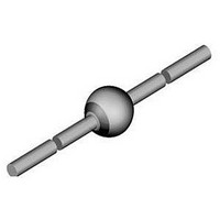
BYW84-TAP Vishay, BYW84-TAP Datasheet - Page 2

BYW84-TAP
Manufacturer Part Number
BYW84-TAP
Description
Bridge Rectifier
Manufacturer
Vishay
Datasheet
1.BYW82-TAP.pdf
(4 pages)
Specifications of BYW84-TAP
Reel Quantity
2500
Current Rating
3A
Forward Voltage
1V
Mounting Type
Surface Mount
Forward Current If
3A
Package / Case
SOD-64
Capacitance
40pF
Product
Standard Recovery Rectifier
Configuration
Single
Reverse Voltage
600 V
Forward Voltage Drop
1 V
Recovery Time
6 ns
Forward Continuous Current
3 A
Max Surge Current
100 A
Reverse Current Ir
1 uA
Mounting Style
SMD/SMT
Maximum Operating Temperature
+ 175 C
Minimum Operating Temperature
- 55 C
Lead Free Status / RoHS Status
Lead free / RoHS Compliant
Available stocks
Company
Part Number
Manufacturer
Quantity
Price
Part Number:
BYW84-TAP
Manufacturer:
VISHAY/威世
Quantity:
20 000
BYW82, BYW83, BYW84, BYW85, BYW86
Vishay Semiconductors
TYPICAL CHARACTERISTICS (T
www.vishay.com
162
Fig. 2 - Max. Average Forward Current vs. Ambient Temperature
ELECTRICAL CHARACTERISTICS (T
PARAMETER
Forward voltage
Reverse current
Breakdown voltage
Diode capacitance
Reverse recovery time
Reverse recovery charge
Fig. 1 - Max. Thermal Resistance vs. Lead Length
94 9563
16361
3.5
3.0
2.5
2.0
1.5
1.0
0.5
0.0
40
30
20
10
0
0
0
T
PCB: d = 25 mm
R
amb
20 40
thJA
5
= 70 K/W
- Ambient Temperature (°C)
I - Lead Length (mm)
DiodesAmericas@vishay.com, DiodesAsia@vishay.com,
10
60 80 100 120 140 160 180
For technical questions within your region, please contact one of the following:
15
T
L
I
R
l
= constant
I
V
half sinewave
R
I = 10 mm
F
= 100 μA, t
R
I
thJA
20
F
= 1 A, dI/dt = 5 A/μs, V
= V
= 0.5 A, I
amb
= 25 K/W
V
l
F
l
RRM
Standard Avalanche Sinterglass
R
V
TEST CONDITION
= 1 A, dI/dt = 5 A/μs
25
R
= V
= 25 °C, unless otherwise specified)
= 4 V, f = 1 MHz
V
RRM
amb
p
R
R
I
/T = 0.01, t
F
30
= 1 A, i
= V
= 3 A
, T
= 25 °C, unless otherwise specified)
RRM
j
= 100 °C
R
= 0.25 A
p
R
Diode
= 0.3 ms
= 50 V
Fig. 4 - Max. Reverse Power Dissipation vs. Junction Temperature
SYMBOL
V
C
Q
V
(BR)
t
t
I
I
R
R
rr
rr
F
D
rr
16360
DiodesEurope@vishay.com
Fig. 3 - Forward Current vs. Forward Voltage
16363
0.001
0.01
100
350
300
250
200
150
100
0.1
50
10
0
1
25
0
MIN.
-
-
-
-
-
-
-
-
T
T
j
j
50
= 175 °C
- Junction Temperature (°C)
V
0.4
F
- Forward Voltage (V)
75
TYP.
0.8
0.1
3.5
4.5
40
5
8
P
at 80 % V
-
-
R
T
100
-Limit
j
= 25 °C
1.2
P
at 100 % V
Document Number: 86051
V
R
125
R
-Limit
R
= V
MAX
1600
7.5
10
60
12
RRM
1
1
5
1.6
Rev. 1.7, 25-Aug-10
150
R
175
2.0
UNIT
μC
μA
μA
pF
μs
μs
V
V


