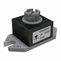
HFA135NH40PBF Vishay, HFA135NH40PBF Datasheet

HFA135NH40PBF
Specifications of HFA135NH40PBF
Available stocks
Related parts for HFA135NH40PBF
HFA135NH40PBF Summary of contents
Page 1
... T = 100°C Maximum Power Dissipation Operating Junction and Storage Temperature Range STG J Limited by junction temperature L = 100μH, duty cycle limited by max T Document Number: 94050 HFA135NH40PbF Ultrafast, Soft Recovery Diode Case Styles HALF-PAK (D-67) J Bulletin PD-21150 06/06 Max Units 400 V 275 A ...
Page 2
... HFA135NH40PbF Bulletin PD-21150 06/06 Electrical Characteristics (per Leg Parameters V Cathode Anode BR Breakdown Voltage, V Max. Forward Voltage FM I Max. Reverse Leakage Current RM C Junction Capacitance T L Series Inductance S Dynamic Recovery Characteristics @ T Parameters t Reverse Recovery Time rr I Peak Recovery Current RRM Q Reverse Recovery Charge ...
Page 3
... FM 100 1 Fig Typical Junction Capacitance vs 100 150 200 250 300 350 DC Forward Current - I (A) F(AV) HFA135NH40PbF Bulletin PD-21150 06/06 150°C 125°C 25°C 200 300 400 Reverse Voltage - V (V) R Fig Typical Reverse Current vs. Reverse Voltage 25°C ...
Page 4
... HFA135NH40PbF Bulletin PD-21150 06/06 450 400 200A, 125°C 350 135A, 125°C 300 250 50A, 125°C 200 150 200A, 25°C 135A, 25°C 100 50 50A, 25°C 0 100 dI dt (A/μs) F/ Fig Typical Reverse Recovery vs. di 6000 5000 200A, 125°C 4000 135A, 125° ...
Page 5
... THERMAL RESPONSE ) 0.001 1E-005 0.0001 Fig Maximum Thermal Impedance Z ADJUST Fig Reverse Recovery Parameter Test Circuit Document Number: 94050 0.001 0.01 0 Rectangular Pulse Duration (sec) 1 Characteristics thJC Reverse Recovery Circuit V = 200V R 0.01 Ω 70µH D.U. /dt dif/dt F IRFP250 G S HFA135NH40PbF Bulletin PD-21150 06/ www.vishay.com 5 ...
Page 6
... HFA135NH40PbF Bulletin PD-21150 06/ /dt - Rate of change of current through zero F crossing Peak reverse recovery current RRM Reverse recovery time measured from zero rr crossing point of negative going I a line passing through 0.75 I extrapolated to zero current Fig Reverse Recovery Waveform and Definitions L = 100µH ...
Page 7
... Dimensions in millimeters and (inches PbF International Rectifier 1 - Average Current Rating Not Isolated Half-pack 4 - Voltage Rating (400V Lead-Free 6 Data and specifications subject to change without notice. Qualification Standards can be found on IR's Web site. HFA135NH40PbF Bulletin PD-21150 06/06 TAC Fax: (310) 252-7309 06/06 www.vishay.com 7 ...
Page 8
... Except as provided in Vishay's terms and conditions of sale for such products, Vishay assumes no liability whatsoever, and disclaims any express or implied warranty, relating to sale and/or use of Vishay products including liability or warranties relating to fitness for a particular purpose, merchantability, or infringement of any patent, copyright, or other intellectual property right. ...


