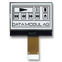
BTHQ128064AVD-COG-FSTF-LED05 W BATRON, BTHQ128064AVD-COG-FSTF-LED05 W Datasheet - Page 9

BTHQ128064AVD-COG-FSTF-LED05 W
Manufacturer Part Number
BTHQ128064AVD-COG-FSTF-LED05 W
Description
LCD MODULE, 128X64, GRAPHIC
Manufacturer
BATRON
Datasheet
1.BTHQ128064AVD-COG-FSTF-LED05_W.pdf
(18 pages)
Specifications of BTHQ128064AVD-COG-FSTF-LED05 W
Lcd Display Type
FSTN
Pixel Size (h X W)
0.349mm X 0.418mm
Interface Type
Serial
Viewing Area (h X W)
31mm X 50.6mm
Supply Voltage
3.3V
External Depth
1.8mm
External
RoHS Compliant
Display Mode
Transflective
Svhc
No SVHC (15-Dec-2010)
Rohs Compliant
Yes
Backlighting Colour
White
Pixel Pitch (h X W)
0.364mm X 0.433mm
3. Interface signals
DATA MODUL AG Landsberger Str. 322 80687 München Tel.: 089/ 56017-0 Fax 089/ 56017-119
Pin No.
(BTHQ128064AVD-COG-FSTF-LED05-White)
10
12
13
14
15
11
1
2
3
4
5
6
7
8
9
Symbol
VOUT
VDD
VSS
C2+
C1+
C86
C2-
C1-
C3-
P/S
V5
V4
V3
V2
V1
This is the parallel data input/serial data input switch terminal.
P/S = HIGH: Parallel data input.
P/S = LOW: Serial data input.
The following applies depending on the P/S status:
When P/S = LOW, D0 to D5 are HZ. D0 to D5 may be HIGH, LOW or Open.
RD(E) and WR(R/W) are fixed to either HIGH or LOW.
With serial data input, RAM display data reading is not supported.
This is the MPU interface switch terminal.
C86=HIGH: 6800 Series MPU interface.
C86=LOW: 8080 MPU interface.
This is multi-level power supply for liquid crystal drive.
Voltage levels are determined based on VDD, and must maintain the relative
magnitudes shown below.
VDD (=V0)
Master operation When the power supply turns ON, the internal power supply
circuits produce V1 to V4 voltages shown below. The voltage setting are
selected using the LCD bias set command.
For 1/7 bias: V1=(1/7)xV5, V2=(2/7)xV5, V3=(5/7)xV5, V4=(6/7)xV5.
DC/DC voltage converter. Connects a capacitor between this terminal and C2–
terminal.
DC/DC voltage converter. Connects a capacitor between this terminal and C2+
terminal.
DC/DC voltage converter. Connects a capacitor between this terminal and C1+
terminal.
DC/DC voltage converter. Connects a capacitor between this terminal and C1–
terminal.
DC/DC voltage converter. Connects a capacitor between this terminal and C1+
terminal.
power supply for the step-up voltage circuit for the liquid crystal drive.
DC/DC voltage converter. Connects a capacitor between this terminal and VSS.
0 V pin connected to the system ground (GND) and this is also the reference
Power supply for logic(+3.3V).
HIGH
LOW
P/S
Data/Command
Table 2(a): Pin Assignment
V1 V2 V3 V4 V5
D/C(A0)
D/C(A0)
VL-FS-COG-BTD12864-04 REV. A
(BTHQ 128064AVD-FSTF-06-LED02white-COG)
JULY/2003
PAGE 9 OF 18
D0 to D7
SI (D7)
Description
Data
Read/Write Serial Clock
Write only
RD, WR
SCL (D6)
www.data-modul.de


