HDSM-533F Avago Technologies US Inc., HDSM-533F Datasheet - Page 2
HDSM-533F
Manufacturer Part Number
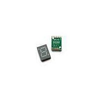
HDSM-533F
Description
DISPLAY, SEVEN SEGMENT, 14.22MM, YELLOW
Manufacturer
Avago Technologies US Inc.
Type
Moduler
Datasheet
1.HDSM-531C.pdf
(9 pages)
Specifications of HDSM-533F
No. Of Digits / Alpha
1
Character Size
14.22mm
Led Color
Yellow
Common Connection
Common Cathode
Luminous Intensity
20mcd
Forward Current If
20mA
Forward Voltage
2.1V
Number Of Digits/alpha
1
Size / Dimension
0.75" L x 0.49" W x 0.15" H (19.00mm x 12.50mm x 3.75mm)
Digit/alpha Size
0.56" (14.22mm)
Display Type
7-Segment
Common Pin
Common Cathode
Color
Yellow
Voltage - Forward (vf) Typ
2.1V
Current - Test
10mA
Millicandela Rating
20mcd
Wavelength - Peak
591nm
Power Dissipation (max)
65mW
Package / Case
10-SMD
Number Of Digits
1
Illumination Color
Yellow
Operating Voltage
2.1 V
Maximum Operating Temperature
+ 105 C
Minimum Operating Temperature
- 40 C
Package Type
SMD
Product Length (mm)
12.5mm
Product Height (mm)
3.75mm
Product Depth (mm)
19mm
Digit Size (in)
.56in
Character Displayed
Numeric
Viewing Area Length (mm)
8.1mm
Viewing Area Height (mm)
14.22mm
Emitting Color
Yellow
Test Current (it)
10mA
Forward Current
25mA
Dominant Wave Length
589nm
Power Dissipation
65mW
Total Thickness
3.15mm
Reverse Voltage
5V
Mounting
Surface Mount
Operating Temperature Classification
Industrial
Pin Count
10
Configuration
Common Cathode
Number Of Elements
8
Peak Wavelength
591nm
Reverse Current
100uA
Rohs Compliant
Yes
Lead Free Status / RoHS Status
Lead free / RoHS Compliant
Lead Free Status / RoHS Status
Lead free / RoHS Compliant, Lead free / RoHS Compliant


Pin Connection (Common Anode)
Internal Circuit Diagram (Common Anode)
Absolute Maximum Ratings @ T
2
PIN No
1
2
3
4
5
6
7
8
9
10
Parameter
Power Dissipation Per Segment
Peak Forward Current Per Segment
( 1/10 Duty Cycle. ,0.1ms pulse width)
Continuous Forward Current Per Segment
Derating Linearly From 25°C Per Segment
Reverse Voltage Per Segment
Operating Temperature Range
Storage Temperature Range
Connection
Cathode E
Cathode D
Common Anode
Cathode C
Cathode DP
Cathode B
Cathode A
Common Anode
Cathode F
Cathode G
A
=25°
Green/Yellow/Red/Orange
65
100
25
0.25
5
Pin Connection (Common Cathode)
Internal Circuit Diagram (Common Cathode)
PIN No
1
2
3
4
5
6
7
8
9
10
-40°C to +105°C
-40°C to +105°C
Connection
Anode E
Anode D
Common Cathode
Anode C
Anode DP
Anode B
Anode A
Common Cathode
Anode F
Anode G
Unit
mW
mA
mA
mA/ °C
V
Related parts for HDSM-533F
Image
Part Number
Description
Manufacturer
Datasheet
Request
R

Part Number:
Description:
DISPLAY 1DIGIT YLW CA 0.28"
Manufacturer:
Avago Technologies US Inc.
Datasheet:
Part Number:
Description:
DISPLAY 1DIGIT ORN CA 0.28"
Manufacturer:
Avago Technologies US Inc.
Datasheet:

Part Number:
Description:
DISPLAY 1DIGIT RED CC 0.28"
Manufacturer:
Avago Technologies US Inc.
Datasheet:
Part Number:
Description:
DISPLAY 1DIGIT YLW CC 0.28"
Manufacturer:
Avago Technologies US Inc.
Datasheet:
Part Number:
Description:
DISPLAY 1DIGIT ORN CC 0.28"
Manufacturer:
Avago Technologies US Inc.
Datasheet:
Part Number:
Description:
DISPLAY 1DIGIT RED CA 0.39"
Manufacturer:
Avago Technologies US Inc.
Datasheet:
Part Number:
Description:
DISPLAY 1DIGIT YLW CA 0.39"
Manufacturer:
Avago Technologies US Inc.
Datasheet:
Part Number:
Description:
DISPLAY 1DIGIT ORN CA 0.39"
Manufacturer:
Avago Technologies US Inc.
Datasheet:
Part Number:
Description:
DISPLAY 1DIGIT RED CC 0.39"
Manufacturer:
Avago Technologies US Inc.
Datasheet:
Part Number:
Description:
DISPLAY 1DIGIT YLW CC 0.39"
Manufacturer:
Avago Technologies US Inc.
Datasheet:
Part Number:
Description:
DISPLAY 1DIGIT ORN CC 0.39"
Manufacturer:
Avago Technologies US Inc.
Datasheet:
Part Number:
Description:
DISPLAY 1DIGIT GRN CA 0.28"
Manufacturer:
Avago Technologies US Inc.
Datasheet:
Part Number:
Description:
DISPLAY 1DIGIT GRN CC 0.28"
Manufacturer:
Avago Technologies US Inc.
Datasheet:
Part Number:
Description:
DISPLAY 1DIGIT GRN CA 0.39"
Manufacturer:
Avago Technologies US Inc.
Datasheet:
Part Number:
Description:
DISPLAY 1DIGIT GRN CC 0.39"
Manufacturer:
Avago Technologies US Inc.
Datasheet: