HDSP-701A Avago Technologies US Inc., HDSP-701A Datasheet

DISPLAY, SEVEN SEGMENT, 17.3MM, RED

HDSP-701A

Manufacturer Part Number
HDSP-701A
Description
DISPLAY, SEVEN SEGMENT, 17.3MM, RED
Manufacturer
Avago Technologies US Inc.
Datasheet

Specifications of HDSP-701A

No. Of Digits / Alpha
1
Character Size
17.27mm
Led Color
Red
Common Connection
Common Anode
Luminous Intensity
2.1mcd
Forward Current If
20mA
Forward Voltage
1.8V
Millicandela Rating
2.1mcd
Internal Connection
Common Anode
Size / Dimension
0.70" L x 0.50" W x 0.25" H (17.80mm x 12.70mm x 6.30mm)
Color
Red
Configuration
5 x 7
Voltage - Forward (vf) Typ
1.8V
Display Type
5 x 7 Dot Matrix
Number Of Digits
1
Illumination Color
Red
Wavelength
643 nm
Common Pin
Common Anode
Operating Current
23 mA
Maximum Operating Temperature
+ 85 C
Minimum Operating Temperature
- 40 C
Rohs Compliant
Yes
Lead Free Status / RoHS Status
Lead free / RoHS Compliant
Lead Free Status / RoHS Status
Lead free / RoHS Compliant, Lead free / RoHS Compliant
17.3 mm (0.68 inch) General Purpose
5x7 Dot Matrix Alphanumeric Displays
Data
HDSP-70xE Series, HDSP-71xE Series
HDSP-70xG Series, HDSP-71xG Series
HDSP-70xA Series, HDSP-71xA Series
Description
These displays have a 17.3 mm (0.68 inch) character
height and use industry standard size and pin-out.
The devices are available in either common row
anode or common row cathode configurations. The
displays come in either gray or black face paint and are
available in a choice of high efficiency red (HER) or green
colors or AlGaAs.
These parts are subjected to Outgoing Quality Assurance
(OQA) inspection with an AQL of 0.065% for functional
and visual/cosmetic defects.
For optimal intensity performance, please consider our
industrial grade displays:
• HDSP-L20x
• HDSP-540x
• HDSP-L10x
Devices
Notes:
1. For details, please contact your local Avago components sales office or an authorized distributor.
HER HDSP-
701E
703E
711E
713E
Sheet
Green HDSP-
701G
703G
711G
713G
AlGaAs HDSP-
701A
703A
711A
713A
Features
• 5 x 7 dot matrix font
• Viewable up to 12 meters
• X-Y stackable
• Industry standard pin-out
• Choice of colors
• Choice of face paint colors
• Design flexibility
• Categorized for luminous intensity
• Green categorized for color
Applications
• Suitable for indoor use
• Not recommended for industrial applications, i.e., op-
• Extreme temperature cycling not recommended
7.6 mm (0.3 in.) Dual-in-Line (DIP) leads on 2.54 mm
(0.1 in.) centers
Red or Green or AlGaAs
Gray or black
Common row anode or common row cathode
erating temperature requirements exceeding 85°C or
Below -40°C
17.3 mm Gray Surface Common Row Anode
17.3 mm Gray Surface Common Row Cathode
17.3 mm Black Surface Common Row Anode
17.3 mm Black Surface Common Row Cathode
Description
[1]
[2]

Related parts for HDSP-701A

HDSP-701A Summary of contents

Page 1

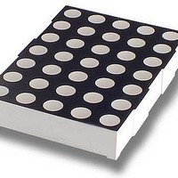
... Data Sheet HDSP-70xE Series, HDSP-71xE Series HDSP-70xG Series, HDSP-71xG Series HDSP-70xA Series, HDSP-71xA Series Description These displays have a 17.3 mm (0.68 inch) character height and use industry standard size and pin-out. The devices are available in either common row anode or common row cathode configurations. The ...

Page 2

... ROW 7 ANODE 7 COLUMN 4 CATHODE 8 COLUMN 5 CATHODE 9 ROW 4 ANODE 10 COLUMN 3 CATHODE 11 ROW 2 ANODE 12 ROW 1 ANODE HDSP-70XE Internal Circuit Diagram 15.24 (0.600) 2.54 (0.10) 8 – 3 (0.118) 8 – 2.5 (0.098) 12 – ∅ 0.5 (0.02) COMMON ROW CATHODE HDSP-703E/713E/ PIN 703G/713G/703A/713A 1 ROW 1 CATHODE 2 ROW 2 CATHODE ...

Page 3

... Symbol Min. I 1.289 V l PEAK [ 1. V-M AlGaAs Green HDSP-701A/ HDSP-701G/ 703A/711A/ 711G/703G/ 713A 713G 75 75 125 90 [3] [ –40 to +85 –40 to +85 –40 to +85 – 250 250 Test Typ. Max. Units Conditions 2.500 mcd mA, ...

Page 4

... Parameter Luminous Intensity/Dot [1] (Digit Average) Peak Wavelength 701G Dominant Wavelength 711G Forward Voltage 703G 713G [3] Reverse Voltage V R Luminous Intensity Matching Ratio AlGaAs Devices HDSP- Parameter Luminous Intensity/Dot [1] (Digit Average) Peak Wavelength 701A Dominant Wavelength 711A Forward Voltage 703A 713A [3] Reverse Voltage V R Luminous Intensity Matching Ratio Notes: 1. The digits are categorized for luminous intensity. The intensity category is designated by a letter on the side of the package. 2. The dominant wavelength, ld, is derived from the CIE chromaticity diagram and represents the single wavelength which defines the color of the device. ...

Page 5

... Figure 4. Relative Efficiency (Luminous Intensity Per Unit Current Per Dot) vs. Peak Current Per Dot. HER GREEN – FORWARD VOLTAGE – HDSP-70XE fig 2 RED GREEN AlGaAs 100 I – PEAK FORWARD CURRENT PEAK PER SEGMENT – mA HDSP-70XE fig 4 ...

Page 6

Intensity Bin Limits (mcd at 50 mA, 20% Duty Factor) High Efficiency Red [2] Bin name Min. E 1.289 F 1.934 G 2.900 H 4.350 Green [2] Bin name Min. H ...

Related keywords