DD-160128FC-1A DENSITRON, DD-160128FC-1A Datasheet - Page 3
DD-160128FC-1A
Manufacturer Part Number
DD-160128FC-1A
Description
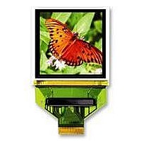
DISPLAY, OLED, RGB, 160X128
Manufacturer
DENSITRON
Datasheet
1.DD-160128FC-1A.pdf
(45 pages)
Specifications of DD-160128FC-1A
Screen Size
36.83mm
Resolution
160 X 128
Viewing Area (h X W)
25.02mm X 30.78mm
Pixel Size (h X W)
0.164mm X 0.04mm
Voltage Rating
2.8V
External Depth
1.7mm
External Length / Height
30.8mm
External
RoHS Compliant
Svhc
No SVHC (15-Dec-2010)
Rohs Compliant
Yes
Connector Type
EVK-Connect-010
Interface Type
Parallel, Serial


SYNCOAM Co., Ltd. SEPS525 Version: 0.2
3. Pin Description
WRB/RWB
Pin Name
EXPORT1
VSYNCO
DOTCLK
ENABLE
DB[17:0]
G[127:0]
RESETB
HSYNC
S[479:0]
VSYNC
OSCA1
OSCA2
VDDIO
VDDH
RDB/E
VSDH
TEST1
VSSH
VDD
IREF
CPU
CSB
VSS
RS
PS
Number
Of Pins
480
128
18
1
1
1
1
1
1
1
1
1
2
2
2
1
1
1
1
1
1
1
1
1
1
1
I/O
I/O
O
O
O
O
O
I
I
I
I
I
I
I
I
‐
‐
‐
‐
‐
‐
‐
I
I
I
I
I
VSS or VDD
VSS or VDD
VSS or VDD
Oscillation‐
Connected
Resistor
POWER
POWER
POWER
POWER
POWER
Resistor
PANEL
PANEL
POVER
MPU
MPU
MPU
MPU
MPU
MPU
To
‐
‐
‐
‐
‐
‐
Selects the CPU type
Selects parallel/Serial interface type
Selects the SEPS525.
Selects the data / command
For an 80‐system bus interface, read strobe signal(active low)
For an 68‐system bus interface, bus enable strobe(active high)
For an 80‐system bus interface, write strobe signal(active low)
For an 68‐system bus interface, read/write select
Serves as a 18_bit bi‐directional data bus
Fix unused pins to the VSS level
Fine adjustment for oscillation
Tie TBD ㏀ ohms to OSCA1 between OSCA2
Reset SEPS525(active low)
SEPS525 Display column outputs
SEPS525 Display row outputs
Data, Scan Driver Power Supply(8V ~ 18V)
Scan Driver Ground
Data Driver Ground
MPU I/F PAD Power Supply(1.6 ~ 3.3V)
Logic power supply(2.4V ~ 3.3V)
Logic ground.
Tie 70 ㏀ to VSS
Selects the test mode
OSC Test
Vertical Sync. Output
Vertical Sync. Input when RGB mode is selected
Horizontal Sync. Input when RGB mode is selected
Dot clock Input when RGB mode is selected
Video enable Input when RGB mode is selected
When using SPI, fix it to VDD or VSS level
When the external clock mode is selected, OSCA1 is used
Low : 80‐Series CPU, High : 68‐Series CPU
Low : serial, High : parallel
Low : SEPS525 is selected and can be accessed
High : SEPS525 is not selected and cannot be accessed
Low : command, High : parameter / data
When using SPI, fix it to VDD or VSS level
Low : Write, High : Read
external clock input
PS
1
0
8_bit bus : DB[17:10]
9_bit bus : DB[17:9]
16_bit bus : DB[17:10], DB[8:1]
18_bit bus : DB[17:0]
DB[17] SCL : Synchronous clock input
DB[16] SDI : Serial data input
DB[15] SDO : Serial data output
Description
Description
3/45
Related parts for DD-160128FC-1A
Image
Part Number
Description
Manufacturer
Datasheet
Request
R

Part Number:
Description:
DISPLAY, OLED, RGB, 160X128
Manufacturer:
DENSITRON
Datasheet:
Part Number:
Description:
62M4129
Manufacturer:
DENSITRON
Datasheet:

Part Number:
Description:
LCD MODULE, 128X240, YELLOW/GREEN
Manufacturer:
DENSITRON
Datasheet:

Part Number:
Description:
LCD MODULE, 128X240, BLUE
Manufacturer:
DENSITRON
Datasheet:

Part Number:
Description:
PMOLED, 128*128, COLOUR
Manufacturer:
DENSITRON
Datasheet:

Part Number:
Description:
DISPLAY, OLED, 128X32, BLUE
Manufacturer:
DENSITRON
Datasheet:
Part Number:
Description:
DISPLAY, OLED, 128X32, YLW
Manufacturer:
DENSITRON
Datasheet:
Part Number:
Description:
PMOLED, 128*64, WHITE
Manufacturer:
DENSITRON
Datasheet:
Part Number:
Description:
DISPLAY, OLED, 128X64, YELLOW
Manufacturer:
DENSITRON
Datasheet:
Part Number:
Description:
128 x 240 PIXEL INDUSTRIAL TOUCH MONITOR
Manufacturer:
Densitron Corporation
Part Number:
Description:
64 x 240 PIXEL INDUSTRIAL TOUCH MONITOR
Manufacturer:
Densitron Corporation
Part Number:
Description:
320 x 240 PIXEL INDUSTRIAL TOUCH MONITOR
Manufacturer:
Densitron Corporation
Part Number:
Description:
320 x 240 PIXEL INDUSTRIAL TOUCH MONITOR
Manufacturer:
Densitron Corporation
Part Number:
Description:
132 Seg / 65 Com Driver & Controller For Stn Lcd
Manufacturer:
Densitron Corporation
Datasheet: