18-052.0055 EAO, 18-052.0055 Datasheet
18-052.0055
Specifications of 18-052.0055


Related parts for 18-052.0055


18-052.0055 Summary of contents
Page 1
... Switches and Indicators 18 18 ...
Page 2
... Switches and Indicators Index Series 18 Description Product Assembly Product Range Technical Data Technical Drawing / Dimension / Layout Circuit Drawing 430 01.2000 - pushbuttons for standard mounting - pushbuttons for flush mounting - accessories / spare parts Page 431 Page 432 Page 433 Page 434 Page 435 ...
Page 3
... Description General Notes The series 18 comprises compact indicators for direct connection to 2. VDC and illuminated pushbuttons with maintained or momentary action. The illuminated pushbutons are equipped with a snap-action swit- ching system with normally open or normally closed contacts. The dimensions of the front are mm dia. ...
Page 4
... Product Assembly illuminated-/pushbutton illuminated-/pushbutton, round for flush mounting 432 01.2000 1 lens 2 switch housing 3 fixing nut 1 lens 2 switch housing 3 front panel 4 front ring bezel 5 front ring bezel bracket 6 fixing nut 18 ...
Page 5
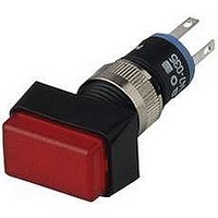
... ST 18-041.0055 18-051.0055 18-031.0055 red ST 18-041.0052 18-051.0052 18-031.0052 yellow ST 18-041.0054 18-051.0054 18-031.0054 green ST 18-042.0055 18-052.0055 18-032.0055 red ST 18-042.0052 18-052.0052 18-032.0052 yellow ST 18-042.0054 18-052.0054 18-032.0054 green ST 18-040.0055 18-050.0055 18-030.0055 red ST 18-040.0052 18-050.0052 18-030.0052 yellow ST 18-040.0054 18-050.0054 18-030.0054 part no ...
Page 6
... ST 18-081.0052 18-061.0052 yellow ST 18-081.0054 18-061.0054 24 VDC/20 mA green ST 18-082.0055 18-062.0055 red ST 18-082.0052 18-062.0052 yellow ST 18-082.0054 18-062.0054 2,2 VDC/20 mA green ST 18-080.0055 18-060.0055 red ST 18-080.0052 18-060.0052 yellow ST 18-080.0054 18-060.0054 436 19 mm dia. part no. SA 1NC main ST 18-268.035 mom ST 18-168.035 1NO main ST 18-267 ...
Page 7
... 19 mm dia. colour part no. black 18-962.0 green 18-962.5 grey 18-962.8 red 18-962.2 white 18-962.9 yellow 18-962 dia. e part no. 18-932.0 0,001 18-932.5 0,001 18-932.8 0,001 18-932.2 0,001 18-932.9 0,001 18-932.4 0,001 9 mm dia. e part no. 18-931.5 0,001 18-931.2 0,001 18-931.4 0,001 part no. 18-982.0 0,001 18-982 ...
Page 8
... colour part no. flat translucent, matt green 18-961.5 red 18-961.2 yellow 18-961 dia. material colour part no. plastic black 18-920.3 plastic black colour part no. black 19-948 part no. 18-981.5 0,001 18-981.2 0,001 18-981.4 0,001 part no. 18-920.2 0,006 18-920.1 0,006 9 mm dia. e part no. 19-949.0 0,001 ...
Page 9
... Ncm pin orientation part no. axial 18-945 5 3 right-angled 18-946 6 4 part no. 18-910 part no. 19-905 18 e 0,001 0,001 e 0,002 e 18 0,011 437 01.2000 ...
Page 10
... VAC, 50 Hz, 1 min. between all terminals and earth, as per IEC 512-2-11 electrical life >= 500.000 cycles of operation at 30 VDC/100 mA to IEC 512-5, Test 9c power consumption 20 mA 438 01.2000 switch rating 10 A/100 V to 100 VAC/VDC volume resistance <= 100 m starting value (initial) IEC 512-2, Test ...
Page 11
... Technical Drawing, Dimension, Layout technical drawing 1 indicator page 433 2 illuminated-/pushbutton page 433 3 indicator for flush mounting page 434 4 illuminated-/pushbutton for flush mounting page 434 18 18 439 01.2000 ...
Page 12
... PCB plug-in base page 437 mounting dimension 1 indicator, illuminated-/pushbutton page 433 2 indicator for flush mounting, illuminated-/pushbutton for flush mounting page 434 components layouts 1 indicator, illuminated-/pushbutton page 433 2 indicator for flush mounting, illuminated-/pushbutton for flush mounting page 434 440 01.2000 18 ...
Page 13
... Technical Drawing, Dimension, Layout 3 PCB plug-in base page 437 4 PCB plug-in base page 437 18 18 441 01.2000 ...
Page 14
... Circuit Drawing circuit drawing 442 01.2000 18 ...