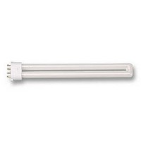
DSE984 OSRAM, DSE984 Datasheet - Page 58

DSE984
Manufacturer Part Number
DSE984
Description
LAMP, DULUX, S/E, CW, 9W
Manufacturer
OSRAM
Datasheet
1.DD1082.pdf
(82 pages)
Specifications of DSE984
Supply Voltage
230V
Base Type
2G7
Power Rating
8W
Luminous Flux
600lm
Length
144mm
Colour Temperature Typ
5000K
Svhc
No SVHC (15-Dec-2010)
External Diameter
21mm
Lamp Base Type
2G7
Rohs Compliant
Yes
Bulb Diameter
21mm
Lead Free Status / RoHS Status
Lead free / RoHS Compliant
Economical long-life light sources with plug-in bases.
Compact Fluorescent Lamps OSRAM DULUX
Technical Guide
5.1.4 Dimming
Reducing the lamp current below the minimum value specified in 5.1.3 can be used
to reduce the luminous flux of the lamp appreciably below its rated value, thereby
dimming the lamp. Please note the following:
- The lamp electrodes must be maintained at emission temperature by a continous
- The lamp voltage at lower discharge current is generally higher than the rated
- The chromaticity coordinate of the light colour may deviate from its specified
In the interest of maximising lamp life, the auxiliary heating current must be matched
to the lamp current. If the auxiliary heating current is too low, the lamp electrodes will
very quickly be destroyed by sputtering. A constant heating current that is too high
will result in excessive emitter evaporisation which leads to end blackening.
Generally speaking, it is not easy to measure the continuous heating current when the
lamp is being operated on an electronic control gear because the current is fed to the
electrodes in the lamp via the two lead wires in a split that depends on the design of
the control gear, and because the lamp current and the auxiliary heating current may
differ in phase, curve shape and frequency. Therefore it is not reasonable to specify
the necessary auxiliary heating current as a function of the lamp current.
The important variable for electrode heating is the electrical heating power P
to the electrode. As
the necessary auxiliary heating current can also be specified as a function of lamp
current by indicating the total of I
currents at an electrode in the lamp. I
tronic control gear.
As the diagram above shows, there is an ideal target setting for the sum of the squa-
res of the two pin currents at which the lamp life will be at it’s optimum. If the sum of
the squares of the pin currents decreases, sputtering will occur at the electrodes and
heating current.
value.
value.
P
Heat
Life
= P
®
Lamp current
Target
+ P
P
Heat
2
Heating current
Pin 1
Pin 1
f (I
+ I
2
2
and I
or
Pin 1
Pin 2
5. Data for control gear manufacturers
, where I
= f (I
Pin 2
+ I
2
Pin 2
2
can be easily measured on elec-
d
, I
)
Pin 1
2
Heat
I
pin 1
2
)
and I
+
f (I
Pin 2
I
2
d
pin 2
2
+ I
are the two pin
2
Heat
)
heat
fed
57


