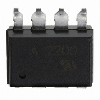
HCPL-2200#300 Avago Technologies US Inc., HCPL-2200#300 Datasheet - Page 9

HCPL-2200#300
Manufacturer Part Number
HCPL-2200#300
Description
OPTOCOUPLER, LOGIC GATE, 3750VRMS
Manufacturer
Avago Technologies US Inc.
Datasheet
1.HCPL-2200-500E.pdf
(13 pages)
Specifications of HCPL-2200#300
No. Of Channels
1
Optocoupler Output Type
Logic Gate
Input Current
5mA
Output Voltage
20V
Opto Case Style
SMD
No. Of Pins
8
Propagation Delay Low-high
0.17µs
Isolation Voltage
3.75kV
Voltage - Isolation
3750Vrms
Number Of Channels
1, Unidirectional
Current - Output / Channel
25mA
Data Rate
2.5MBd
Propagation Delay High - Low @ If
210ns @ 3mA
Current - Dc Forward (if)
10mA
Input Type
DC
Output Type
Tri-State
Mounting Type
Surface Mount, Gull Wing
Package / Case
8-SMD Gull Wing
Lead Free Status / RoHS Status
Contains lead / RoHS non-compliant
Other names
516-1054-5
Available stocks
Company
Part Number
Manufacturer
Quantity
Price
Switching Specifications (AC)
For 0 C T
All Typicals at T
Package Characteristics
*The Input-Output Momentary Withstand Voltage is a dielectric voltage rating that should not be interpreted as an input-output continuous voltage rating. For
the continuous voltage rating refer to the IEC/EN/DIN EN 60747-5-2 Insulation Characteristics Table (if applicable), your equipment level safety specification
or Avago Application Note 1074 entitled “Optocoupler Input-Output Endurance Voltage,” publication number 5963-2203E.
9
Logic Low Output Level
Logic High Output Level
Parameter
Logic High
Common Mode
Transient
Immunity
Logic Low
Common Mode
Transient
Immunity
Parameter
Input-Output Momentary
Withstand Voltage*
Input-Output Resistance
Input-Output Capacitance
Parameter
Propagation Delay Time to
Propagation Delay Time to
Output Enable Time to
Logic High
Output Enable Time to
Logic Low
Output Disable Time from
Logic High
Output Disable Time from
Logic Low
Output Rise Time (10-90%)
Output Fall Time (90-10%)
A
[1]
A
85 C, 4.5 V V
= 25 C, V
|CM
|CM
Sym.
CC
H
L
|
|
= 5 V, I
CC
Sym.
V
R
C
HCPL-2200
HCPL-2219
HCPL-2200
HCPL-2219
20 V, 1.6 mA I
F(ON)
ISO
I-O
I-O
Sym.
Device
t
t
t
t
t
t
PHL
PLH
PZH
PHZ
PZL
PLZ
t
t
r
f
= 3 mA unless otherwise specified.
Min.
3750
Min.
1,000
2,500
F(ON)
1,000
2,500
Min.
Typ.
10
0.6
Typ.
210
160
170
115
105
12
25
28
60
55
15
5 mA, 0.0 mA I
Max.
Max. Units
300
300
V/ s
V/ s
V/ s
V/ s
Units
V rms
Units
ns
ns
ns
ns
ns
ns
ns
ns
pF
|V
|V
|V
|V
CM
CM
CM
CM
F(OFF)
Without Peaking Capacitor
With Peaking Capacitor
Without Peaking Capacitor
With Peaking Capacitor
| = 50 V
| = 400 V
| = 50 V
| = 400 V
RH 50%, t = 1 min.,
T
V
f = 1 MHz, V
A
Test Conditions
I-O
= 25 C
= 500 VDC
0.1 mA.
Test Conditions
Test Conditions
I-O
I
V
T
V
V
T
F
CC
CC
A
A
F
= 0 VDC
= 1.6 mA
= 0 V
= 25 C
= 25 C
= 5 V
= 5 V
Fig.
5, 10
5, 10
11
11
Fig.
Fig.
5, 6
5, 6
7, 9
7, 8
7, 9
7, 8
Note
Note
Note
3, 8
4, 5
4, 5
6
6
3
3


