TWINSPOTNM ETERNA, TWINSPOTNM Datasheet - Page 2
TWINSPOTNM
Manufacturer Part Number
TWINSPOTNM
Description
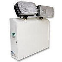
EMERGENCY LIGHT, TWIN SPOT, 2X20W
Manufacturer
ETERNA
Datasheet
1.TWINSPOTNM.pdf
(2 pages)
Specifications of TWINSPOTNM
Length
310mm
Width
310mm
Depth
70mm
Ip/nema Rating
IP20
Svhc
No SVHC (15-Dec-2010)
Base Type
12V 20W BA 15S
External Depth
70mm
External Length / Height
310mm
External Width
310mm
Height
310mm
Lamp Base Type
12V
Rohs Compliant
Yes
Lead Free Status / RoHS Status
Lead free / RoHS Compliant


Read this first:
>
>
>
>
>
>
>
>
>
>
>
>
Safety markings:
This light fitting must be installed in accordance
with the Building Regulations making reference
to the Wiring Regulations BS7671. The Building
Regulations may be obtained from HMSO or viewed
and downloaded from www.communities.gov.uk
following the link for Building Regulations.
Switch off the mains before commencing installation
and remove the appropriate circuit fuse.
Your emergency fittings should have their own
separate mains supply circuit and should not share
their supply with other lighting or electrical devices.
This product is suitable for installation on flammable
surfaces ( indicated by the "F" in a triangle )
Suitable for indoor use only.
Before making fixing hole(s), check that there are no
obstructions hidden beneath the mounting surface
such as pipes or cables.
The chosen location of your new fitting should allow
for the product to be securely mounted and safely
connected to the mains supply.
Ensure that the fitting will be accessible after
installation for maintenance.
If the location of your new fitting requires the
provision of a new electrical supply, the supply must
conform with the requirements of the Building
Regulations making reference to the Wiring
Regulations ( see above ).
Make connections to the electrical supply in
accordance with the following code:
This product must be connected to Earth.
You are advised at every stage of your installation to
double-check any electrical connections you have
made. After you have completed your installation
there are electrical tests that should be carried out:
these tests are specified in the Wiring Regulations
( BS7671 ) referred to in the Building Regulations. If
in doubt, consult a qualified electrician.
Live - L
Neutral - N
Earth - E
Installation:
1)
2)
3)
4)
5)
6)
7)
8)
9)
10) Write the current date on the battery pack.
11) Replace the batteries and reconnect. Ensure that the
12) Fit the battery fuse into the fuse holder on the PCB.
13) Replace the front cover and secure with the two
14)
15)
Operation checks:
Periodic testing should be carried out monthly by
simulating a failure of supply, causing the fitting to be
energised from it’s battery. Interruption of the supply
should be carried out by the operation of a local keyswitch
or other isolation device. During this period all fittings
should be examined visually to ensure that they are
functioning correctly. At the end of the test period the
supply shall be restored and all indicator lamps or devices
checked to ensure that the normal supply has been
restored.
The duration of the simulated failure shall be as follows:-
Undo the screws on each side of the front panel and
lift off.
Disconnect and remove the batteries noting the
connections.
Choose which side of the fitting you need to make
your cable entry and knock out the slug.
Using the back of the fitting as a template, mark the
position of the fixing holes on your mounting surface.
Make fixing holes and fit plugs as appropriate.
Secure the back of the fitting to the mounting surface
using suitable fixings ( not supplied ).
Fit a cable gland ( not supplied ) into the cable entry
hole.
Thread the supply cable through the gland and into
the fitting.
Make connection to the mains supply according to
the colour code opposite. Take care not to leave any
strands protruding from the terminals and to tighten
all terminals securely. Ensure also that the terminals
clamp onto the bare wire and not onto the insulation.
batteries are connected with correct polarity, i.e.: Red
+, Black –.
Fuses are supplied in a small plastic bag fixed to the
battery lead.
remaining screws.
Restore the power supply.
Check that the Green LEDs that indicate charging
and continuity in the two lamps are all lit.
……… contd
Each month:
Isolate the power supply and check the light is illuminated.
This test should last for no more than 45 minutes.
Endorse the test record form supplied.
Every six months:
Isolate the power supply and check that the light is still
illuminated after 1 hour. Endorse the test record form.
Once each year:
Isolate the power supply and check that the light is still
illuminated after 3 hours. Endorse the test record form.
Important notes:
Please keep this instruction booklet and test record in a safe
place. A fire officer or other authorised person may want to see
your record of inspection and testing.
The ballast and control gear must be operated only within the
enclosure supplied. The gear must not be operated outside of the
enclosure.
The battery charging circuit and control gear are separated from
the mains by SELV.
When energised by a constant mains supply, the battery will be
constantly charged. On failure of the constant mains supply, the
fitting will switch automatically by relay from battery charging to
battery discharge powering the lamps. Both the mains and battery
supplies incorporate fuse protection: see fitting for location and
rating.
Related parts for TWINSPOTNM
Image
Part Number
Description
Manufacturer
Datasheet
Request
R


Part Number:
Description:
TWIN AX ADAPTER J-J
Manufacturer:
AMPHENOL RF
Datasheet:

Part Number:
Description:
CONN KEYING PLUG TWIN LEAF .040
Manufacturer:
Tyco Electronics
Datasheet:
Part Number:
Description:
CONN LOCKING KEY TWIN LEAF CRIMP
Manufacturer:
Tyco Electronics
Datasheet:
Part Number:
Description:
CONN KEYING PLUG TWIN LEAF .050
Manufacturer:
Tyco Electronics
Datasheet:

Part Number:
Description:
TWIN LEAF TERM. STRIP CSTL
Manufacturer:
Tyco Electronics
Datasheet:

Part Number:
Description:
TWIN LEAF TERMINAL STRIP
Manufacturer:
Tyco Electronics
Datasheet:

Part Number:
Description:
TWIN LEAF L.P. TERM.
Manufacturer:
Tyco Electronics
Datasheet:

Part Number:
Description:
CONN TWIN LEAF 20-24AWG GOLD
Manufacturer:
Tyco Electronics
Datasheet:

Part Number:
Description:
Twin transistors equipped with different model chips(6P small MM)
Manufacturer:
NEC
Datasheet:
Part Number:
Description:
Twin transistors equipped with different model chips(6P small MM)
Manufacturer:
NEC
Datasheet:

Part Number:
Description:
TRANSFORMER, 12V, 105VA, 5WAY
Manufacturer:
ETERNA
Datasheet: