ASMT-LR50 Avago Technologies US Inc., ASMT-LR50 Datasheet - Page 32
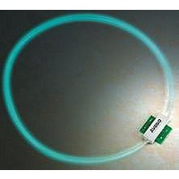
ASMT-LR50
Manufacturer Part Number
ASMT-LR50
Description
LED Light Tube
Manufacturer
Avago Technologies US Inc.
Series
ASMT-Lx50r
Specifications of ASMT-LR50
Led Module Type
Plug & Play
Led Color
Red
Wavelength Typ
630nm
Power Module Configuration
Strip
Supply Voltage
5V
Forward Current @ Test
20mA
Power Rating
153mW
Operating Temperature Range
-30°C To +60°C
Color
Red
Voltage Rating
5V
Current
20mA
Lens Type
Clear
Lens Style/size
-
Configuration
Circular
Mounting Type
Chassis Mount
Lead Free Status / RoHS Status
Lead free / RoHS Compliant


LED Solutions
Device Selection Guide
Envisium 0.25W Power PLCC-4 Surface Mount LED
Notes:
. The dominant wavelength, λ
. θ
. The luminous intensity, I
4. Φ is the total luminous flux output as measured with an integrating sphere after the device has stabilized.
5. Flux tested at mono pulse conditions.
Envisium 0.5W Power PLCC-4 Surface Mount LED
Notes:
. The dominant wavelength, λ
. θ
. The luminous intensity, I
4. Φ is the total luminous flux output as measured with an integrating sphere after the device has stabilized.
5. Flux tested at mono pulse conditions.
Intensity Bin Select (X
An individual reel will contain parts from one half bin only
0
Part Number
ASMC-PRB9-TV005
ASMC-PHB9-TW005
ASMC-PAB9-TV005
Part Number
ASMC-QAB-TAC0E
ASMC-QHB-TCD0E
X
0
4
5
7
8
9
2
/
/
X
3
is the off-axis angle where the luminous intensity is / the peak intensity.
is the off-axis angle where the luminous intensity is / the peak intensity.
V
V
, is measured at the mechanical axis of the lamp package. The actual peak of the spatial radiation pattern may not be aligned with this axis.
, is measured at the mechanical axis of the lamp package. The actual peak of the spatial radiation pattern may not be aligned with this axis.
Min. I
Full Description
half bins starting from X
4 half bins starting from X
5 half bins starting from X
half bins starting from X
4 half bins starting from X
5 half bins starting from X
Color
AllnGaP Red
AllnGaP Red
Orange
AllnGaP Amber
Color
Amber
Red Orange
2
D
D
X
, is derived from the CIE Chromaticity Diagram and represents the color of the device.
, is derived from the CIE Chromaticity Diagram and represents the color of the device.
3
)
V
Bin
Typ.
Dominant
Wavelength
λD (nm)1
60.0
60.0
60.0
67.0
67.0
67.0
59.0
59.0
59.0
Typ.
Dominant
Wavelength
λD (nm)
59.5
69.
1
Typ.
Angle
2θ1/2 (°)2
0
0
0
0
0
0
0
0
0
Typ.
Angle
2θ1/2 (°)
0
0
Viewing
Viewing
2
Intensity
Bin
V
V
W
W
W
X
V
V
W
Flux Bin
A
B
C
C
D
Intensity Bin Limits and Typical Flux
Tolerance of each bin limit = ± %
Min. IV
(mcd)
60.00
790.00
000.00
000.00
00.00
580.00
60.00
790.00
000.00
Min. Flux (lm) Max. Flux
4.
5.5
7.0
7.0
9.0
Bin ID
V
V
W
W
X
X
Max. IV
(mcd)
000.00
60.00
600.00
600.00
00.00
500.00
000.00
60.00
600.00
(lm)
5.5
7.0
9.0
9.0
.5
Min. (mcd)
75.00
900.00
5.00
400.00
800.00
40.00
Total Flux ΦV
(mlm)4,5
Typ.
600.00
00.00
–
400.00
5000.00
–
000.00
800.00
–
Typ. Vf (V)
.64
.64
Max. (mcd)
900.00
5.00
400.00
800.00
40.00
850.00
Typ. VF
(V)
.8
.8
.8
.8
.8
.8
.8
.8
.8
Test Current
(mA)
50
50
50
50
50
Test
Current
(mA)
50
50
50
50
50
50
50
50
50
Dice
Technology
AlInGaP
AlInGaP
Related parts for ASMT-LR50
Image
Part Number
Description
Manufacturer
Datasheet
Request
R

Part Number:
Description:
LED RD/GN/BL 0.5W 4-PLCC
Manufacturer:
Avago Technologies US Inc.
Datasheet:

Part Number:
Description:
LED RED 622NM 145DEG 0603 SMD
Manufacturer:
Avago Technologies US Inc.
Datasheet:

Part Number:
Description:
LED RD/GN/BL 0.5W 4-PLCC
Manufacturer:
Avago Technologies US Inc.
Datasheet:

Part Number:
Description:
LED CHIPLED 0.45MM ORANGE 0603
Manufacturer:
Avago Technologies US Inc.
Datasheet:

Part Number:
Description:
LAMP PCB POLYLED ALINGAP AMB SMD
Manufacturer:
Avago Technologies US Inc.
Datasheet:
Part Number:
Description:
LAMP PCB POLYLED ALINGAP GRN SMD
Manufacturer:
Avago Technologies US Inc.
Datasheet:

Part Number:
Description:
LAMP PCB POLYLED ALINGAP RED SMD
Manufacturer:
Avago Technologies US Inc.
Datasheet:
Part Number:
Description:
LAMP PCB POLYLED INGAN BLUE SMD
Manufacturer:
Avago Technologies US Inc.
Datasheet:

Part Number:
Description:
LED IND LONG LIFE BLUE 2PLCC
Manufacturer:
Avago Technologies US Inc.
Datasheet:

Part Number:
Description:
LED IND LONG LIFE WHITE 2PLCC
Manufacturer:
Avago Technologies US Inc.
Datasheet:
Part Number:
Description:
LED IND LONG LIFE GREEN 2PLCC
Manufacturer:
Avago Technologies US Inc.
Datasheet:

Part Number:
Description:
LAMP AF DOME ALINGAP ORANGE SMD
Manufacturer:
Avago Technologies US Inc.
Datasheet:

Part Number:
Description:
LED IND LONG LIFE WHITE 4PLCC
Manufacturer:
Avago Technologies US Inc.
Datasheet:
Part Number:
Description:
LAMP AF DOME ALINGAP ORANGE SMD
Manufacturer:
Avago Technologies US Inc.
Datasheet:

Part Number:
Description:
LAMP AF DOME INGAN GREEN SMD
Manufacturer:
Avago Technologies US Inc.
Datasheet: