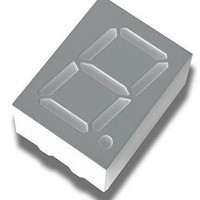
HDSP-513A Avago Technologies US Inc., HDSP-513A Datasheet - Page 9

HDSP-513A
Manufacturer Part Number
HDSP-513A
Description
S4,PCB,0.56S,ALGAAS,CC :
Manufacturer
Avago Technologies US Inc.
Type
Moduler
Specifications of HDSP-513A
Rohs Compliant
YES
Number Of Digits/alpha
1
Size / Dimension
0.67" L x 0.49" W x 0.31" H (17.10mm x 12.40mm x 8.00mm)
Digit/alpha Size
0.56" (14.22mm)
Display Type
7-Segment
Common Pin
Common Cathode
Color
Red
Voltage - Forward (vf) Typ
1.85V
Current - Test
10mA
Millicandela Rating
6.5mcd
Wavelength - Peak
660nm
Power Dissipation (max)
30mW
Package / Case
10-DIP (0.600", 15.24mm)
Number Of Digits
1
Character Size
14.2 mm
Illumination Color
Red
Wavelength
568 nm
Operating Voltage
1.85 V
Operating Current
15 mA
Maximum Operating Temperature
+ 85 C
Minimum Operating Temperature
- 35 C
Luminous Intensity
6500 ucd
Package Type
DIP
Product Length (mm)
12.4mm
Product Height (mm)
8mm
Product Depth (mm)
17.1mm
Digit Size (in)
.56in
Character Displayed
Numeric
Viewing Area Length (mm)
7.9mm
Viewing Area Height (mm)
14.22mm
Emitting Color
Red
Forward Voltage
2V
Test Current (it)
10mA
Forward Current
15mA
Dominant Wave Length
643nm
Power Dissipation
30mW
Total Thickness
8mm
Reverse Voltage
5V
Mounting
Through Hole
Operating Temperature Classification
Industrial
Pin Count
10
Configuration
Common Cathode
Number Of Elements
8
Peak Wavelength
660nm
Lead Free Status / RoHS Status
Lead free / RoHS Compliant
Lead Free Status / RoHS Status
Lead free / RoHS Compliant
Figure 13. Maximum allowable average or DC cur-
rent vs. ambient temperature.
Figure 15. Relative luminous intensity vs. DC forward
current.
For product information and a complete list of distributors, please go to our website:
Avago, Avago Technologies, and the A logo are trademarks of Avago Technologies Limited in the United States and other countries.
Data subject to change. Copyright © 2005-2008 Avago Technologies Limited. All rights reserved. Obsoletes 5988-2968EN
AV02-1363EN - June 21, 2008
Yellow
25
20
15
10
I
5
0
F
3.5
3.0
2.5
2.0
1.5
1.0
0.5
0
– FORWARD CURRENT FOR SEGMENT – mA
0
T
0
YELLOW
A
– AMBIENT TEMPERATURE – °C
20
5
10
40
15
60
20
25
80
30
100
35
www.avagotech.com
Figure 14. Forward current vs. forward voltage.
Figure 16. Relative effi ciency (luminous intensity per
unit current) vs. peak current.
120
100
80
60
40
20
0
0
1.4
1.2
1.0
0.8
0.6
0.4
0.2
0
0
0.5
I
V
PEAK
F
5 10 15 20 25 30 35 40 45 50
– FORWARD VOLTAGE – V
1.0
– PEAK FORWARD CURRENT
PER SEGMENT – mA
1.5
2.0
2.5
3.0
3.5


