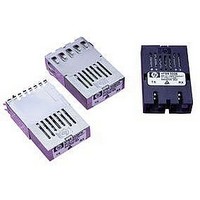
HFBR-5205 Avago Technologies US Inc., HFBR-5205 Datasheet

HFBR-5205
Available stocks
Related parts for HFBR-5205
HFBR-5205 Summary of contents
Page 1
AFBR-5205Z ATM Multimode Fiber Transceivers for SONET OC-3/SDH STM-1 in Low Cost 1x9 Package Style Data Sheet AFBR-5205Z, AFBR-5205AZ, AFBR-5205APZ, AFBR-5205ATZ, AFBR-5205PZ, AFBR-5205TZ, AFBR-5205PEZ 1300 Description The AFBR-5200Z family of transceivers from Avago Technologies provide the system ...
Page 2
Receiver Sections The receiver sections of the AFBR-5205Z series utilize InGaAs PIN photodiodes coupled to a custom silicon transimpedance preamplifier IC. These are packaged in the optical subassem- bly portion of the receiver. These PIN/preamplifier combina- tions are coupled to ...
Page 3
ELECTRICAL SUBASSEMBLY DIFFERENTIAL DATA OUT SINGLE-ENDED SIGNAL QUANTIZER IC DETECT OUT DIFFERENTIAL DATA IN DRIVER IC TOP VIEW Figure 1a. ST block diagram. 25.40 MAX. (1.000) AFBR-5xxxZ A DATE CODE (YYWW) SINGAPORE + 0.08 0.75 - 0.05 3.30 ± 0.38 ...
Page 4
MAX. (1.000) AFBR-5xxxxZ DATE CODE (YYWW) SINGAPORE 12.0 MAX. (0.471) 2.6 ± 0.4 (0.102 ± 0.016) 0.46 (0.018) NOTE 1 20.32 17.4 [(8x (2.54/0.100)] (0.800) (0.685) 22.86 21.4 (0.900) (0.843) 3.6 (0.142) 1.3 (0.051) NOTE 1: PHOSPHOR BRONZE IS ...
Page 5
MAX. SLOT DEPTH +0.1 0.25 -0.05 9.8 MAX (0.386) +0.004 0.010 -0.002 3.3 ± 0.38 (0.130 ± 0.015) 20.32 +0.25 (0.80) 0.46 -0. +0.010 0.018 -0.002 8X 2.54 20.32 23.8 (0.100) (0.800) (0.937) ...
Page 6
MAX. +0.1 0.25 -0. +0.004 0.010 -0.002 9.8 MAX. 3.3 ± 0.38 (0.386) (0.130 ± 0.015) 20.32 +0.25 (0.800) 0.46 -0. +0.010 0.018 -0.002 20.32 23.8 2.54 8x (0.800) (0.937) (0.100) 1.3 2x ...
Page 7
The following information is provided to answer some of the most common questions about the use of these parts. Transceiver Optical Power Budget versus Link Length Optical Power Budget (OPB) is the available optical power for a fiber optic link ...
Page 8
The transceivers may be used for other applications at signaling rates different than 155 Mbps with some variation in the link optical power budget. Figure 5 gives an indication of the typical performance of these products at different rates. These ...
Page 9
Solder and Wash Process Compatibility The transceivers are delivered with protective process plugs inserted into the duplex SC or duplex ST connector receptacle. This process plug protects the Rx NO INTERNAL CONNECTION AFBR-520xZ TOP VIEW ...
Page 10
Board Layout – Decoupling Circuit and Ground Planes It is important to take care in the layout of your circuit board to achieve optimum performance from these transceivers. Figure 7 provides a good example of a schematic for a power ...
Page 11
Board Layout – Mechanical For applications interested in providing a choice of either a duplex duplex ST con- nector interface, while utilizing the same pinout on the printed circuit board, the ST port needs to protrude from ...
Page 12
PCB BOTTOM VIEW DIMENSIONS ARE IN MILLIMETERS (INCHES). ALL DIMENSIONS ARE ± 0.025 mm UNLESS OTHERWISE SPECIFIED. Figure 8b. Dimensions shown for mounting module with extended shield to panel. Electromagnetic Interference (EMI) Most equipment designs utilizing these high ...
Page 13
TRANSMITTER r/f 2.5 OUTPUT OPTICAL 120 RISE/FALL TIMES – ns 3.0 100 1260 1280 1300 1320 1340 – TRANSMITTER OUTPUT OPTICAL C CENTER WAVELENGTH –nm AFBR-5205Z TRANSMITTER TEST RESULTS OF ...
Page 14
BOTTOM SIDE OF PCB DIMENSIONS ARE IN MILLIMETERS (INCHES). ALL DIMENSIONS ARE ± 0.025 mm UNLESS OTHERWISE SPECIFIED. Figure 8c. Dimensions shown for mounting module flush to panel. 14 1.98 THICKER PANEL WILL RECESS MODULE. (0.078) THINNER PANEL ...
Page 15
... AFBR-520XZ family in a pre-existing 1x13 or 2x11 pinout system design configuration or when connectored to various test equipment. 1. HFBR-0319 – Evaluation Test Fixture Board: This test fixture converts +5 V ECL 1x9 transceivers to –5 V ECL BNC Coax Connections so that direct connections to ...
Page 16
AFBR-5205Z Series Absolute Maximum Ratings Parameter Storage Temperature Lead Soldering Temperature Lead Soldering Time Supply Voltage Data Input Voltage Differential Input Voltage Output Current AFBR-5205Z Series Recommended Operating Conditions Parameter Ambient Operating Temperature* Supply Voltage Data Input Voltage - Low ...
Page 17
AFBR-5205Z Series Transmitter Electrical Characteristics ( 4. 5.25 V Parameter Supply Current Power Dissipation Data Input Current - Low Data Input Current - High *Applies to AFBR-5205Z Series ...
Page 18
AFBR-5205Z/-5205AZ/-5205ATZ/-5205PZ/-5205TZ/-5205PEZ Transmitter Optical Characteristics ( 4. 5.25 V Parameter Output Optical Power BOL 62.5/125 0.275 Fiber EOL Output Optical Power BOL 50/125 ...
Page 19
AFBR-5205Z/-5205AZ/-5205ATZ/-5205PZ/-5205TZ/-5205PEZ Receiver Optical and Electrical Characteristics ( 4. 5.25 V Parameter Input Optical Power Minimum at Window Edge Input Optical Power Minimum at Eye Center Input Optical Power ...
Page 20
... The test window time-width is as follows: HFBR-5205 is 3.32 ns. • Transmitter operating with a 155.52 MBd, 77.5 MHz square-wave, input signal to simulate any cross-talk present between the transmitter and receiver sections of the transceiver ...
Page 21
For product information and a complete list of distributors, please go to our website: Avago, Avago Technologies, and the A logo are trademarks of Avago Technologies Limited in the United States and other countries. Data subject to change. Copyright © ...


