RF620RA RF Solutions, RF620RA Datasheet - Page 3
RF620RA
Manufacturer Part Number
RF620RA
Description
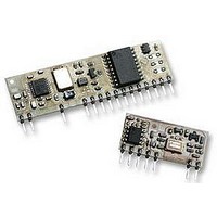
RECEIVER, SMART, RADIO
Manufacturer
RF Solutions
Datasheet
1.RF620RA.pdf
(7 pages)
Specifications of RF620RA
Svhc
No SVHC (15-Dec-2010)


DS620-2 August ‘06
RF620R - Pin Description
RF620R - Typical application circuit
Pin No
11
13
14
15
16
17
19
20
21
22
23
24
25
1
2
3
7
GND
Vcc
1
GND-digital
\Serial Data
Vcc-digital
GND-RF
GND-RF
GND-AF
Vcc-RF
O/P-AF
3
\Learn
MCLR
Name
spare
spare
RSSI
\RTS
\LED
O/P1
O/P2
ANT
&
SmartRadio Transmitter / Receiver
7
Description
+5V Supply Voltage – RF section.
RF Ground.
Connect Antenna to this input.
RF Ground.
AF Ground.
Received Signal Strength Indicator (RSSI)
Raw Data output from RF receiver (CMOS/TTL signal)
+5V Supply Voltage – digital section.
AF Ground – digital section.
Pulls Microcontroller into reset if connected to Ground
May be left unconnected if not required (internally tied high)
Serial data output, active low
/RTS input, active low
Dual function:
Programming Switch input, When grounded places the module into ‘learn’ mode.
External LED output, Indicates data reception, and programming status.
leave unconnected
leave unconnected
Data Output 1. (has a 220Ω series resistor)
Data Output 2. (has a 220Ω series resistor)
©2006 Reg. No. 227 4001, ENGLAND
11
RF620R
15
20
22
25
Serial data output,
CMOS/TTL Level
RTS input
O/P 2
LED drive example
Page 3
Status
470R
LED
O/P 1
1k
Learn Switch
Vcc
RF620T
RF620R
Related parts for RF620RA
Image
Part Number
Description
Manufacturer
Datasheet
Request
R

Part Number:
Description:
REMOTE CONTROL, 1CH, 433MHZ
Manufacturer:
RF Solutions
Datasheet:

Part Number:
Description:
TRANSMITTER, KEELOQ, 1SW, KEYFOB
Manufacturer:
RF Solutions
Datasheet:

Part Number:
Description:
RECEIVER, RX, MINI, SUPER-REGEN
Manufacturer:
RF Solutions
Datasheet:

Part Number:
Description:
RADIO SYSTEM, 1CH, 1XTX 1XRX, 1000M
Manufacturer:
RF Solutions
Datasheet:

Part Number:
Description:
RECEIVER, AM, CERAMIC
Manufacturer:
RF Solutions
Datasheet:

Part Number:
Description:
IC ENCODER TRANSMITTER RF 8DIP
Manufacturer:
RF Solutions
Datasheet:

Part Number:
Description:
IC DECODER RECEIVER RF 18DIP
Manufacturer:
RF Solutions
Datasheet:

Part Number:
Description:
IC ENCODER 3 DGTL I/O SOT23-6
Manufacturer:
RF Solutions
Datasheet:

Part Number:
Description:
IC ENCODER 3 DGTL I/O 8-PDIP
Manufacturer:
RF Solutions
Datasheet:

Part Number:
Description:
IC DECODER 3 DGTL I/O 8-PDIP
Manufacturer:
RF Solutions
Datasheet:

Part Number:
Description:
IC DECODER 3 DGTL I/O 8-SOIC
Manufacturer:
RF Solutions
Datasheet:

Part Number:
Description:
118 SERIES AM REMOTE CONTROL SYSTEMS.
Manufacturer:
RF Solutions Ltd.