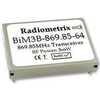
BIM3B-869.85-64 RADIOMETRIX, BIM3B-869.85-64 Datasheet

BIM3B-869.85-64
Specifications of BIM3B-869.85-64
Related parts for BIM3B-869.85-64
BIM3B-869.85-64 Summary of contents
Page 1
... PDAs, organisers and laptops Handheld terminals EPOS equipment, barcode scanners, belt clip printers Data loggers Audience response systems In-building environmental monitoring and control Security and fire alarms Restaurant ordering systems Vehicle data up/download Radiometrix Ltd, BiM3B Data Sheet BiM3B Fig. 1: BiM3B-869.85-64 page 1 ...
Page 2
... Functional overview The transmit section of the BiM3B consists of a frequency modulated crystal locked PLL feeding a buffer amplifier and RF filter select line controls operation. The transmitter achieves full RF output typically within 1ms of this line being pulled low. Modulation is applied at the TXD input and may be either a serial digital stream toggling between 0V and 3V (digital drive high level analogue waveform with the same peak limits (linear drive) ...
Page 3
... DC +ve supply pin. +2.9 to +16.0 volts @ <17mA (@ 5mW). The supply should be clean, <20mV side view (through can) RF GND 1 Antenna 2 RF GND pin Weight: 7g (typ.) Radiometrix Ltd, BiM3B Data Sheet Function Power down (<10 A) Receiver enabled Transmitter enabled Self test loop-back* top view (without can 30. Fig ...
Page 4
... RSSI output, max indication RSSI range IF bandwidth Image rejection (f -21.4MHz rejection (10.7MHz) Local osc. leakage, conducted Baseband bandwidth @ -3dB Baseband bandwidth @ -3dB AF output signal level Radiometrix Ltd, BiM3B Data Sheet - + +100 C -0.3V to +16V -9V to +16V -0.3V to +Vcc 50V DC, +10dBm RF pin min. typ ...
Page 5
... DC offset errors on the AF output. The time constant of the adaptive data slicer in the BiM3B is set at a reasonable compromise to allow the use of low code speeds where necessary whilst keeping settling times acceptably fast for battery- economised operation. RXD output on pin 12 is “ ...
Page 6
... Received Signal Strength Indicator (RSSI) The BiM3B receiver incorporates a wide range RSSI which measures the strength of an incoming signal over a range of approximately 60dB. This allows assessment of link quality and available margin and is useful when performing range tests ...
Page 7
... A simple test for interference is to monitor the receiver RSSI output voltage, which should be the same regardless of whether the microcontroller or other logic circuitry is running or in reset. Two types of antenna are recommended for use with the BiM3B: Whip (¼-wave). This consists simply of a piece of wire or rod connected to the module at one end. The ...
Page 8
... Care should also be taken to ensure that this effect does not increase the radiated power in any direction beyond that allowed by type approval regulations. Where this occurs the antenna may need to be relocated. In extreme cases a resistive attenuator of appropriate value may be required between the module and antenna. Radiometrix Ltd, BiM3B Data Sheet wire, rod, PCB track combination of these L (mm) = 71250 / freq(MHz) shortened wire, rod, PCB track etc ...
Page 9
... The equipment in which the BiM3B is used must carry all necessary external labelling to meet the requirements of the R&TTE directive. 4) The BiM3B has not been tested with antennas having gains greater than that of a quarter-wave whip. The use of such antennas may require further R&TTE approval. ...
Page 10
... Radiometrix Ltd, BiM3B Data Sheet [ERP] POWER RF page 10 ...
Page 11
... Copyright notice This product data sheet is the original work and copyrighted property of Radiometrix Ltd. Reproduction in whole or in part must give clear acknowledgement to the copyright owner. Limitation of liability The information furnished by Radiometrix Ltd is believed to be accurate and reliable. Radiometrix Ltd reserves the right to make changes or improvements in the design, specification or manufacture of its subassembly products without notice ...


