EZBEE RF Solutions, EZBEE Datasheet - Page 4
EZBEE
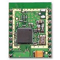
Manufacturer Part Number
EZBEE
Description
MODULE, ZIGBEE, EZBEE
Manufacturer
RF Solutions
Datasheet
1.EZBEE.pdf
(7 pages)
Specifications of EZBEE
Svhc
No SVHC (15-Dec-2010)


2. OEM products incorporating EasyBee must
3.
OUI number / MAC address
All IEEE 802.15.4 devices such as EasyBee must use a
unique 8-byte MAC address. The first 3 bytes (the ‘OUI’
number) are licensed to a company by IEEE for an
annual fee. The licensee is then free to uniquely assign
the remaining 5 bytes.
FlexiPanel Ltd can provide MAC addresses under its
OUI license for the transceivers it manufactures. OEMs
therefore do not need to apply for an OUI number.
FlexiPanel Ltd’s OUI number is 00-15-C8.
For R&D purposes (i.e. in the lab or classroom), the
following MAC addresses may be used:
For commercial purposes, contact FlexiPanel Ltd or
your distributor for an allocation of MAC addresses.
Radio Frequency
Optimizing RF Performance
The integral antenna supplied with Pixie is a modified
quarter wave F antenna with efficiency of approximately
70%. This is comparable to a dipole and about as high
as physically possible.
approximately omnidirectional.
Free space range is approximately 120m. In-building
ranges of 20m to 40m would normally be expected.
The
performance. Avoid the use of metal enclosures. Gray
and black plastics should be used with caution. They
often contain carbon, which degrades performance
considerably. To test for the presence of carbon, heat
the plastic in a microwave oven for one minute. If it
melts, it probably contains carbon.
A high location is recommended, particularly for
avoiding interference from transient objects such as
passers-by and their cellphones. Microwave ovens are
particularly problematic for the short periods in which
they and operational.
antennas
polarizations are the same. In a mesh network, a highly
attenuating medium such as a floor may be bridged by
placing two routers close to each other, one on either
side of the barrier.
p4
00:15:C8:38:41:00:00:00 to 00:15:C8:38:41:00:FF:FF
include an external label containing the
following text legible to the naked eye:
Changes or modifications to the module may
void its certification.
20-Sep-06
enclosure
in
Contains Transmitter Module
the
FCC ID:UGAZBMR10
employed
EasyBee DS480-11
same
Where possible, orient all the
direction
Its radiation pattern is
may
affect
so
© FlexiPanel Ltd
that
antenna
their
Mechanical
PCB Layout
For PCB pad layout, refer to the engineering drawing on
page 6. Note how the pads on the main board protrude
out from beneath the module. This provides a point to
apply heat when manually soldering and also for
continuity testing.
ensures a large reservoir of solder is available to the
actual contact area.
If soldered using a reflow oven, the surface mount
module may be treated like a BGA package.
quality of the joint may be tested by checking for
continuity between the pad on the upper side of the
board and the protruding part of the pad on the main
board.
If soldering manually, use the following procedure:
Location on main board
The module should be located so that the antenna abuts
the edge of the board or overhangs it. It should be
placed so that it is unlikely that interfering items such as
metal, water, cellphones, body tissue, etc, can come
into close proximity.
Table 2. Attenuation of typical bulk materials
Material
Reinforced concrete floor
Brick wall with window
Office wall
Metal cabinet
5mm potting compound
Vegetation
In general attenuating most noticeably when closest to the antenna.
1. Tin the contact pads on the module, trying to get
2. Tin contact pads on main board.
3. Place the module in position on the main board.
4. Starting with the pads most likely to be in physical
5. Test for continuity between the pad on the upper
6. Rework non-conducting contacts by applying heat
Patents may apply and/or pending
more or less the same amount of solder on each.
Work on a soft surface so that the components on
the topside are not damaged.
contact, apply heat with a soldering iron to the
exposed part of the main board pads. Abut the iron
against the edge of the module so that the heat is
transmitted to the contact area of the pads. After
10-15 seconds, remove heat. Around 90% of pads
should be successfully soldered.
side of the board and the protruding part of the pad
on the main board.
again and a little extra solder.
Compact materials, e.g. humans, have an complex effect,
In addition, the size of the pad
Reduces range by factor of
30
www.FlexiPanel.com
1.25
2
3
2 - 3
1.25 per meter
The
Related parts for EZBEE
Image
Part Number
Description
Manufacturer
Datasheet
Request
R

Part Number:
Description:
RF Switch SPDT 0MHz to 2GHz 27dB 8-Pin SOIC T/R
Manufacturer:
M/A-Com Technology Solutions
Datasheet:
Part Number:
Description:
RF Switch SPST 500MHz to 2GHz 40dB 8-Pin SOIC T/R
Manufacturer:
M/A-Com Technology Solutions
Datasheet:

Part Number:
Description:
RF Switch SPDT 100MHz to 4GHz 14dB 6-Pin SOT-6
Manufacturer:
Skyworks Solutions Inc
Datasheet:
Part Number:
Description:
RF Switch SPST 500MHz to 2.5GHz 10dB 6-Pin SOT-6
Manufacturer:
Skyworks Solutions Inc

Part Number:
Description:
IC ENCODER TRANSMITTER RF 8DIP
Manufacturer:
RF Solutions
Datasheet:

Part Number:
Description:
IC DECODER RECEIVER RF 18DIP
Manufacturer:
RF Solutions
Datasheet:

Part Number:
Description:
IC ENCODER 3 DGTL I/O SOT23-6
Manufacturer:
RF Solutions
Datasheet:

Part Number:
Description:
IC ENCODER 3 DGTL I/O 8-PDIP
Manufacturer:
RF Solutions
Datasheet:

Part Number:
Description:
IC DECODER 3 DGTL I/O 8-PDIP
Manufacturer:
RF Solutions
Datasheet:

Part Number:
Description:
IC DECODER 3 DGTL I/O 8-SOIC
Manufacturer:
RF Solutions
Datasheet:

Part Number:
Description:
118 SERIES AM REMOTE CONTROL SYSTEMS.
Manufacturer:
RF Solutions Ltd.