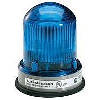
Description
The 104 Series AdaptaBeacon is a UL and cUL listed signaling
appliance in a NEMA 4X and IP65 rated enclosure. CE Marked.
The modules can be panel mounted or conduit mounted.
AdaptaBeacon modules are available in Flashing LED
(104FLED), Steady-On LED (104SLED), Flashing Halogen
(104FINH), Steady-On Halogen (104SINH) or Flashing Strobe
(104ST). The maximum capacitor operating temperature (Tc) is
185°F (85°C).
The modules are available in a variety of colors as listed in
Table 1.
Specifications
Installation
Conduit Mounting (Figure 1)
1. Thread the 18" (45.7 cm) signal wire leads through either
2. Wire the beacon as follows:
Cheshire, CT 06410 203-699-3300 (Ph)
203-699-3365 (Cust. Serv. Fax)
203-699-3078 (Tech. Serv. Fax)
Catalog
Number
104FLED(*)-G1
104FLED(*)-N5
104SLED(*)-G1
104SLED(*)-N5
104FINH(*)-G1
104FINH(*)-G5
104FINH(*)-N5
104SINH(*)-G1
104SINH(*)-G5
104SINH(*)-N5
104ST(*)-N5
*Letter in this position signifies color of the lens. For available colors, see
Table 1.
To prevent electrical shock, ensure that power is
turned off before installing the signal.
1/2" (13mm) or 3/4" (19 mm) conduit into an approved
conduit outlet box. (Product is supplied with a double
threaded - 1/2" (13mm) internal and 3/4" (19mm) external -
conduit hub.)
a.
b.
For AC models, use wire nuts (not supplied) and connect
the signal's black and white wire leads to the power source
wires as shown in Figure 1. Polarity is not relevant.
For DC models, connect the signal's red wire to the
positive power source wire and connect the signal's black
wire to the negative power source wire using wire nuts
(not supplied). Polarity must be observed. Refer to
Figure 1.
120V 50/60 Hz
120V 50/60 Hz
120V 50/60 Hz
120V 50/60 Hz
120V 50/60 Hz
24V 50/60 Hz
24V 50/60 Hz
Voltage
24V DC
24V DC
24V DC
24V DC
WARNING
Current
0.062 A
0.022 A
0.062 A
0.022 A
0.77 A
0.77 A
0.25 A
0.77 A
0.77 A
0.25 A
0.12 A
Installation Instructions for 104 Series AdaptaBeacon
Xenon Strobe Tube
12W Halogen Bulb
12W Halogen Bulb
9W Halogen Bulb
9W Halogen Bulb
9W Halogen Bulb
9W Halogen Bulb
28 LED Cluster
28 LED Cluster
28 LED Cluster
28 LED Cluster
Illumination
Source
Modules in NEMA 4X Enclosures
3. Thread the conduit onto the base of the signal.
4. Turn on power and verify that the signal operates properly.
Panel Mounting (Figure 2)
Note: The integrity of the outdoor, NEMA 4X, and IP65 rating
on the panel assembly at the interface with the 104 Series
AdaptaBeacon relies on the construction and configuration de-
tails of the mounting surface. Installer should evaluate.
1. Place the mounting gasket (supplied) over the hole in the
2. Insert the base through the hole in the panel and screw the
3. Wire the beacon as follows:
4. Turn on power and verify that the signal operates properly.
To avoid risk of injury, install lens before energizing
the unit.
To avoid the risk of injury, do not remove or insert
lamp when unit is energized.
panel and route the signal wires through the gasket and the
hole in the panel.
locking nut (supplied), with the raised locking edge facing
the mounting surface, onto the base to secure the beacon.
a.
b.
For AC models, use wire nuts (not supplied) and connect
the signal's black and white wire leads to the power source
wires as shown in Figure 2. Polarity is not relevant.
For DC models, connect the signal's red wire to the
positive power source wire and connect the signal's black
wire to the negative power source wire using wire nuts
(not supplied). Polarity must be observed. Refer to
Figure 2.
WARNINGS
P-047550-1848 ISSUE 6 © 2003
®