271-U 115V Fluke, 271-U 115V Datasheet - Page 3
271-U 115V
Manufacturer Part Number
271-U 115V
Description
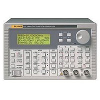
FUNCTION GENERATOR ARB/FREQ/PULSE, 10MHZ
Manufacturer
Fluke
Datasheet
1.271-U_115V.pdf
(4 pages)
Specifications of 271-U 115V
Signal Generator Type
ARB/Frequency/Signal/DDS
Bandwidth
10MHz
Modulation Type
Amplitude/Frequency
Supply Voltage Range
110V To 120V / 220V To 240V
External Height
130mm
Lead Free Status / RoHS Status
na


Operating Modes
Auxiliary Outputs
Inputs
Trigger/burst
Phase coherent signal keying — each positive edge of the trigger signal will produce one burst of the carrier, starting and stopping at the
phase angle specified by the start/stop phase setting
Carrier frequency
Carrier waveforms
Number of cycles
Trigger rep. rate
Source
Gated
Non phase-coherent signal keying — output is On while Gate signal is high and Off while low.
Carrier frequency
Carrier waveforms
Trigger rep. rate
Gate source
Sweep
Carrier waveforms
Sweep mode
Sweep width
Sweep time
Markers
Sweep trigger source
Hop
Up to 16 different “hop” waveforms can be defined in terms of function, frequency, amplitude, offset and duration. Duration setable per
step 1 ms to 60 s.
Start/Stop Phase
Carrier frequency:
Carrier waveforms
Range
Resolution
Accuracy
Trigger Generator
Internal source 0.005 Hz to 50 kHz squarewave adjustable in 20 us steps. 3 digit resolution. Available for external use from TRIG/SWEEP OUT
socket.
Aux Out
CMOS/TTL levels with symmetry and frequency of main output and phase of start-stop phase setting
Trig/Sweep Out
Multi-function output depending upon mode. Except in sweep mode, the output is that of the trigger generator at CMOS/TTL levels from 1 kΩ.
In Sweep mode the output is a 3-level waveform, changing from high (+4 V) to low (0 V) at the start of sweep, with narrow 1 V pulses at
each marker point.
Ext Trig
Frequency range
Signal range
Min. pulse width
VCA In
Frequency range
Signal range
Input impedance
0.1 mHz to 10 MHz
All
1 to 1023 (resolution 1 cycle) or 0.5 to 511.5 (resolution 1/2 cycle)
dc to 50 kHz internal, dc to 1 MHz external
Internal from keyboard or trigger generator. External from EXT TRIG input or remote interface
From 0.1 mHz to 10 MHz
All
dc to 50 kHz internal dc to 1 MHz external
Internal from keyboard or trigger generator. External from EXT TRIG input or remote interface
All
Linear or logarithmic, single or continuous
0.1 mHz to 10 MHz. Phase continuous. Independent setting of the start and stop frequency.
10 ms to 999 s (3 digit resolution)
Two markers variable during sweep. Available at the TRIG/SWEEP OUT socket
The sweep may be free run or triggered from: keyboard, EXT TRIG input, remote interface
0.1 mHz to at least 1 MHz
All
–360 to +360 degrees
1 degree
Typically 1 degree to 30 kHz
DC to 1 MHz
TTL (1.5 V) threshold; maximum input ± 10 V
50 ns
DC - 100 kHz
2.5 V for 100 % level change at maximum output
Typically 6 kΩ
Signal Sources
227