9G1212G1021 SANYO DENKI - SANACE FANS, 9G1212G1021 Datasheet - Page 100
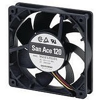
9G1212G1021
Manufacturer Part Number
9G1212G1021
Description
AXIAL FAN, 120MM, 12VDC, 980mA
Manufacturer
SANYO DENKI - SANACE FANS
Datasheet
1.109P0412D602.pdf
(276 pages)
Specifications of 9G1212G1021
External Height
120mm
External Width
120mm
External Depth
38mm
Current Type
DC
Supply Voltage
12VDC
Flow Rate
137CFM
Noise Rating
49dBA
Power Connection Type
Lead Wires
Bearing Type
Ball
Flow Rate - Imperial
137CFM
Rohs Compliant
Yes
Lead Free Status / RoHS Status
Lead free / RoHS Compliant


DC Fans
Thermal speed controlled fans with an external or built-in thermistor
98
External thermistor type
3. If you wish to obtain low or high speed in a process of testing by using a larger equipment regard-
less of the thermistor temperature:
Low speed :
High speed :
1. Overview
For thermal speed controlled fans with an external thermistor, just connect a specified thermistor (or a specified thermistor and a resistor) between the con-
trol wire and the negative wire indicated in Fig. 1, it will enable the fan speed to change automatically according to a predetermined temperature speed speci-
fication and according to temperature changes in an environment where the thermistor is equipped .(Please refe to Fig. 2)
4. Connecting the fan to the thermistor
Sanyo Denki recommends to use connectors, including the power lead of the fan.
Example of Typical connections :place a thermistor on the printed circuit board and connect the fan's power lead and control lead
to the circuit pattern by means of connectors.
5. Typical applications of thermal speed controlled fans with an external thermistor
Here are typical applications of a thermal speed controlled fan with a power supply where two 109P1212H402 fans are used (Fig. 5).
(1) The fan selected was a 109P1212T4H12 thermal speed controlled fan having a performance equal to that of conventional fans at
(2) The relationship between the temperatures of important components and those of the cooling fin can be measured with varied
(3) Next, in view of the thermal design conditions of the equipment, the fan is set to high speed at an ambient temperature of 30℃
A thermistor can therefore be installed at an appropriate position inside your equipment to monitor the internal temperature
changes due to changes in ambient temperature and heatup status (load status) of the equipment. Automatic monitoring can
then specify low speed when the thermistor detects a temperature below TL, high speed when it detects a temperature above TH,
and a speed according to the temperature when it detects a temperature between TL and TH.
Thus, the fan motor detects its own operational status and determines the operating conditions.
As a result, the thermal speed controlled fan with an external thermistor is designed that temperature changes according to the
ambient temperature and operational status of the equipment are detected by the thermistor to control the fan's air flow (speed),
and is near-ideal particularly in designing silent equipment. The fan motor thus meets the three requirements: silence, energy-
saving, and long life.
2. Setting temperatures (TL and TH) in low and high speed
The standard products listed in this catalog are designed to run at a low speed at 28
more when a recommended thermistor is connected between the control wire and the negative wire.
These temperatures (TL and TH) can be changed (as indicated in Table 1) by inserting a resistor in series with the thermistor.
high speed.
loads on the equipment and varied air flows of the fan. Since a correlation was determined, the thermistor can then be placed
on the cooling fin, one of the important components.
and an equipment load of 100%.
Fan
Fig. 3
Printed circuit board of the equipment
Fan
Recommended thermistor
Control
Instead of the thermistor, connect a 10 K
Connect the control wire directly to the negative wire.
( Red )
( Black )
( Brown )
Fig. 1
Resistor Rs
Fig. 4
Control
Thermistor
E
Thermistor
Resistance Rs
(Ω)
2.75K
0.8K
1.5K
2.0K
2.4K
0
Connector
Ω
Table 1
resistor between the control wire and the negative wire.
Temperature setting ( ℃)
31.5
40.5
28
35
38
43
TL
100
TH
50
35
40
45
50
55
60
0
Low speed
Japan Aviation Electronics Industry
Japan Solderless Terminals
Manufacturer
℃
Molex Japan
* For the resistor Rs, use a resistor rated at no less than
* For the thermistor, use a 159-682-86** which are
Japan AMP
TL
1/8W.
manufactured
or below and run at a high speed at 35
Recommended connectors
TH
High speed
Variable speed in linear
XHP-3,SMR-3V-N
IL-G-3S-S3C2-SA
171822-3
5102-3
Model (3-pole)
Thermistor temperature (℃)
Fig. 2
℃
or
Related parts for 9G1212G1021
Image
Part Number
Description
Manufacturer
Datasheet
Request
R

Part Number:
Description:
Plug & Cord Set For AC Fans
Manufacturer:
SANYO DENKI - SANACE FANS
Part Number:
Description:
Plug & Cord Set For AC Fans
Manufacturer:
SANYO DENKI - SANACE FANS
Part Number:
Description:
Plug & Cord Set For AC Fans
Manufacturer:
SANYO DENKI - SANACE FANS
Part Number:
Description:
Plug & Cord Set For AC Fans
Manufacturer:
SANYO DENKI - SANACE FANS
Part Number:
Description:
Plug & Cord Set For AC Fans
Manufacturer:
SANYO DENKI - SANACE FANS
Part Number:
Description:
Plug & Cord Set For AC Fans
Manufacturer:
SANYO DENKI - SANACE FANS
Part Number:
Description:
Plug & Cord Set For AC Fans
Manufacturer:
SANYO DENKI - SANACE FANS
Part Number:
Description:
Plug & Cord Set For AC Fans
Manufacturer:
SANYO DENKI - SANACE FANS
Part Number:
Description:
Plug & Cord Set For AC Fans
Manufacturer:
SANYO DENKI - SANACE FANS
Part Number:
Description:
Plug & Cord Set For AC Fans
Manufacturer:
SANYO DENKI - SANACE FANS
Part Number:
Description:
Plug & Cord Set For AC Fans
Manufacturer:
SANYO DENKI - SANACE FANS

Part Number:
Description:
Finger Guard
Manufacturer:
SANYO DENKI - SANACE FANS
Datasheet: