22-4518-10 Aries Electronics, 22-4518-10 Datasheet
22-4518-10
Manufacturer Part Number
22-4518-10
Description
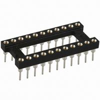
22 PIN SOLDER TAIL DIP SOCKET
Manufacturer
Aries Electronics
Series
518r
Type
DIP, 0.4" (10.16mm) Row Spacingr
Specifications of 22-4518-10
Number Of Positions Or Pins (grid)
22 (2 x 11)
Pitch
0.100" (2.54mm)
Mounting Type
Through Hole
Features
Open Frame
Contact Finish
Gold
Contact Finish Thickness
10µin (0.25µm)
Connector Type
DIP
No. Of Contacts
22
Pitch Spacing
2.54mm
Row Pitch
10.16mm
Contact Termination
Through Hole
Contact Material
Beryllium Copper
Contact Plating
Gold
Svhc
No SVHC (15-Dec-2010)
Product
DIP / SIP Sockets
Mounting Style
PCB
Lead Free Status / RoHS Status
Lead free / RoHS Compliant
Lead Free Status / RoHS Status
Lead free / RoHS Compliant, Lead free / RoHS Compliant
Other names
A406


FEATURES
SPECIFICATIONS
MOUNTING CONSIDERATIONS
• Open Frame allows Efficient Utilization of Board Space with Optimized Cooling
• Choose from Several Pin Styles
• Compatible with Automatic Insertion Equipment
• Side-to-Side and End-to-End Stackable
• Body Material is black UL 94V-0 glass-filled 4/6 Nylon
• Pin Body is Brass Alloy 360 1/2-hard per UNS C36000 ASTM B16-00
• Pin Body Plating 10μ [0.25μm] min. Gold per MIL-G-45204
• 4-fingered Collet Contact is Beryllium-Copper Alloy per UNS C17200 ASTM B194-01
• Contact Plating 200μ [5.08μm] min. 93/7 Tin/Lead per ASTM B545
• Available Plating = Heavy Gold 30μ [0.76μm]
• Contact Current Rating = 3 amps
• Operating Temperature = 221°F [105°C] Tin and Tin/Lead plating = 257°F [125°C] Gold plating
• Insertion Force = 180 grams/pin
• Withdrawal Force = 90 grams/pin
• Normal Force = 140 grams/pin
• Midget Pin Insertion Force = 370 grams/pin
• Midget Pin Withdrawal Force = 150 grams/pin
• Midget Pin Normal Force = 240 grams/pin, based on a 0.018 [0.46] dia. test lead
• Accepts Lead Lengths from 0.100 [2.54] min. and 0.015-0.025 [0.38-0.64] in dia.
• Accepts Midget Pin Lead Lengths from 0.080 [2.03] and up to 0.022 [0.56] dia.
• Suggested PCB Hole Size for Solder Pin Tail and Extra Long Pin = 0.030 ±0.002 [0.76 ±0.05] dia.
• Suggested PCB Hole Size for Midget Pin = 0.040 ±0.002 [1.02 ±0.05] dia.
or
200μ [5.08μm] min. 93/7 Tin/Lead per ASTM B545
or
200μ [5.08μm] min. Tin per ASTM B545 Type 1 over 100μ [2.54μm] min. Nickel per SAE AMS-QQ-N-290
or
200μ [5.08μm] min. Tin per ASTM B545 Type 1
or
10μ [0.25μm] Gold per MIL-G-45204 over 50μ min. [1.27μm] Nickel per SAE AMS-QQ-N-290
PRINTOUTS OF THIS DOCUMENT MAY BE OUT OF DATE AND SHOULD BE CONSIDERED UNCONTROLLED
Series 518 Open Frame Collet
Sockets w/Solder Pin Tails – 1 of 2
FRENCHTOWN, NJ USA
TEL (908) 996-6841 • FAX (908) 996-3891
WWW.ARIESELEC.COM
• INFO@ARIESELEC.COM
12016
Rev. F
Related parts for 22-4518-10
Image
Part Number
Description
Manufacturer
Datasheet
Request
R

Part Number:
Description:
IC & Component Sockets SURFACE MOUNT 22 PIN
Manufacturer:
Aries Electronics
Datasheet:

Part Number:
Description:
IC & Component Sockets OPEN FRAME COLLET SOLDER TAIL 22 PINS
Manufacturer:
Aries Electronics
Datasheet:
Part Number:
Description:
IC & Component Sockets OPEN FRAME COLLET SOLDER TAIL 22 PINS
Manufacturer:
Aries Electronics
Datasheet:
Part Number:
Description:
IC & Component Sockets OPEN FRAME COLLET SOLDER TAIL 22 PINS
Manufacturer:
Aries Electronics
Datasheet:
Part Number:
Description:
IC & Component Sockets OPEN FRAME COLLET SOLDER TAIL 22 PINS
Manufacturer:
Aries Electronics
Datasheet:

Part Number:
Description:
Row-to-Row DIP Adapter Socket
Manufacturer:
ARIES [Aries Electronics, Inc.]
Datasheet:
Part Number:
Description:
5-Pin PLCC Motorola MC68HC11E9-to-56-Pin SDIP Adapter
Manufacturer:
ARIES [Aries Electronics, Inc.]
Datasheet:
Part Number:
Description:
64-Pin DIP-to-PLCC 68-Pin Zilog Z80180 Adapter
Manufacturer:
ARIES [Aries Electronics, Inc.]
Datasheet:
Part Number:
Description:
RoHs/WEEE-Compliant SOIC-to-JEDEC TO Adapter
Manufacturer:
ARIES [Aries Electronics, Inc.]
Datasheet:
Part Number:
Description:
68-Pin PLCC-to-DIP 64-Pin Motorola MC68HC000 Adapter
Manufacturer:
ARIES [Aries Electronics, Inc.]
Datasheet:
Part Number:
Description:
Surface Mount-to-DIP JEDEC SOT-25, SOT-23A-6 Adapter
Manufacturer:
ARIES [Aries Electronics, Inc.]
Datasheet:
Part Number:
Description:
0.5mm 8- and 10-Pin
Manufacturer:
ARIES [Aries Electronics, Inc.]
Datasheet:
Part Number:
Description:
24-Pin SOWIC-to-22-Pin
Manufacturer:
ARIES [Aries Electronics, Inc.]
Datasheet:
Part Number:
Description:
ZIF PGA Test & Burn-in Socket for Any Footprint on Std 13x13 to 21x21 Grid
Manufacturer:
ARIES [Aries Electronics, Inc.]
Datasheet:

22-4518-10 Summary of contents
Page 1
... Accepts Midget Pin Lead Lengths from 0.080 [2.03] and up to 0.022 [0.56] dia. MOUNTING CONSIDERATIONS • Suggested PCB Hole Size for Solder Pin Tail and Extra Long Pin = 0.030 ±0.002 [0.76 ±0.05] dia. • Suggested PCB Hole Size for Midget Pin = 0.040 ±0.002 [1.02 ±0.05] dia. ...
Page 2
... H = Heavy Gold on Collet T = Tin on Collet TL Tin-Lead on Collet M = Midget Solder Tail - Available Gold Collet, Tin Shell MTL = Midget Solder Tail - Available Gold Collet, Tin-Lead Shell Only FRENCHTOWN, NJ USA TEL (908) 996-6841 • FAX (908) 996-3891 WWW.ARIESELEC.COM • INFO@ARIESELEC.COM Centers “Y” Dim. “Z” 1 ...