2510CT Staco Energy Products Company, 2510CT Datasheet - Page 2
2510CT
Manufacturer Part Number
2510CT
Description
Variable Transformer
Manufacturer
Staco Energy Products Company
Type
Knob (Replacement Parts)r
Datasheet
1.2510.pdf
(3 pages)
Specifications of 2510CT
Input Voltage
120V
Output Current
25A
Knob Rotation
CW / CCW
Transformer Mounting
Bench
Secondary Current Nom
25A
No. Of Phases
Single
Primary Voltages
120V
Power Rating
3kVA
Dimensions
6.31 in L x 7.94 in W x 10.56 in H
Product
Variable Transformers
Height
10.56 in
Length
6.31 in
Width
7.94 in
Constant Current Load
25A
Rohs Compliant
Yes
Current Rating
25A
Leaded Process Compatible
No
Output Voltage
140V
Output Voltage Max
120VAC
Lead Free Status / RoHS Status
Lead free / RoHS Compliant


•
++ Line to line voltage
‡
+ Motor driven units use terminal connections for CCW increasing voltage, as viewed from
MANUALLY
OPERATED
3PN2210B
3PN2520B
2520CT-2 M2520CT-2+
2510CT-2 M2510CT-2+ Phase
2510CT-3 M2510CT-3+ Wye
2520CT-3 M2520CT-3+ Wye
2510C-2 M2510C-2+ Three
2510C-3 M2510C-3+ Phase
2510CT M2510CT+ Phase
2510-3
2520C-2 M2520C-2+
2520C-3 M2520C-3+ Phase
2500 Series
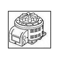
The 2510/2520 Series Variable Transformers represent a com-
pact high current variable transformer design. The 2510, 120
volt unit is rated at 25 amperes for constant current loads; while
the 2520, 240 volt unit is rated at 10 amperes for constant cur-
rent loads. Constant impedance ratings are listed in the specifi-
cations. They can be operated at frequencies between 50 and
2000 Hertz with derating at higher than rated frequency.
Uncased models have the shaft extending from the base end.
This shaft is fully adjustable and can be extended from either
end for general utility mounting. Cased styles are available in
either “C” style (featuring protective screening over the coil
2510-2
520CT
2520-2
2520-3
2510C
2520C
2510
Jumper provided in the standard common position and should be moved or removed as
required.
Unit is fused for the constant current rating at the factory.
the base end. See Figure 23 on page 9 for motor wiring.
If ganged units are used in a system that ordinarily has a common neutral or ground
between source and load, the neutral or ground must be connected to the common ter-
2520
PART NUMBER
M2520CT+
M2510-3+
M2510-2+
M2520-2+
M2520-3+
M2520C+
M2510+
M2510+
M2520+
DRIVEN WIRING VOLTS
MOTOR
Phase
Phase
Single
Single
Delta
Delta
Single
Single
Phase
Series
Single
Phase
Single
Phase
Series
Phase
Three
Three
Three
Open
Open
120++
240++
240++
480++
120
240
120
240
240
120
480
240
120
240
++
++
INPUT
HERTZ
50/60
50/60
50/60
50/60
50/60
50/60
50/60
50/60
50/60
50/60
50/60
50/60
50/60
60
60
60
VOLTS
0-120
0-240
0-140
0-240
0-480
0-240
0-280
0-140
0-280
0-120
0-140
0-240
0-280
0-280
0-280
0-560
0-560
0-280
0-280
0-480
0-560
0-560
AMPS
MAX
22‡
10 ‡
10#
10#
10#
10#
CONSTANT
25
25
10
10
10
25
25
25
25
25
25
10
10
10
10
10
CURRENT
LOAD
OUTPUT
MAX
10.40
12.10
1.20§
2.40§
2.10§
4.20§
KVA
3.00
6.00
3.08
2.40
4.80
4.20
2.80
3.50
7.00
5.20
6.06
2.80
5.60
4.85
8.30
9.70
AMPS
MAX
30
30
13
13
13
—
—
30
30
13
—
—
—
—
—
—
—
—
—
—
—
—
IMPEDANCE
CONSTANT
LOAD
#
§
assembly only) or the “CT” style (which also includes a terminal
box cover with knock-outs to accept conduit).
Motor-driven models are available in single, two, or three
ganged assemblies in cased or uncased styles as identified by
the prefix “M” in the part number. If a motor driven model is
ordered, be sure to prefix the part number with the desired trav-
el time from 0 to maximum of 5, 15, 30 or 60 seconds.
Example: 5M2510CT. The synchronous motor is designed for
operation on 120 volts, 50/60 Hertz, single phase lines and
draws approximately 0.3 amperes.
3.12
6.24
5.40
10.81
MAX
KVA
3.6
7.2
12.5
—
—
minals of the variable transformer assembly. If the system has no neutral, the load must
be balanced or the transformers will be damaged.
Maximum output current in output voltage range from 0 to 25% above line voltage. At high-
er output voltages, the output current must be reduced according to the derating curve,
Figure B, page 6.
Maximum KVA at maximum output voltage and corresponding derated output current.
Maximum KVA for lower voltages may be calculated from derating curve Figure B, page 6.
6.2
—
—
—
—
—
—
—
—
—
—
—
—
INCREASE
ROTATION
VOLTAGE
SHAFT
CCW
CCW
CCW
CCW
CCW
CCW
CCW
CCW
CCW
CCW
CCW
CCW
CCW
CCW
CCW
CCW
CCW
CCW
FOR
CW
CW
CW
CW
CW
CW
CW
CW
CW
CW
CW
CW
CW
CW
CW
CW
CW
CW
CW
CW
CW
CW
CW
CW
(FOR INCREASING VOLTAGE)
AS VIEWED FROM BASE END
INPUT
2-4-2
4-2-4
1-4-1
5-2-5
2-2-2
4-4-4
1-1-1
5-5-5
2-4-2
4-2-4
1-4-1
5-2-5
7-4-7
6-2-6
2-2-2
4-4-4
1-1-1
5-5-5
7-7-7
6-6-6
TERMINAL CONNECTIONS
2-4
2-4
1-4
2-5
2-2
4-4
1-1
5-5
2-4
2-4
1-4
2-5
7-4
6-2
2-2
4-4
1-1
5-5
7-7
6-6
LINE CORD &
RECEPTACLE
LINE CORD &
RECEPTACLE
JUMPER• OUTPUT
2-2-2
4-4-4
2-2-2
4-4-4
2-2-2
4-4-4
2-2-2
4-4-4
2-2-2
4-4-4
2-2
4-4
2-2
4-4
2-2
4-4
2-2
2-2
4-4
2-2
4-4
2-2
2-2
4-4
2-2
4-4
2-2
4-4
4-4
4-4
—
—
—
—
—
—
—
—
—
—
3-3-3
3-4-3
3-4-3
3-2-3
3-4-3
3-2-3
3-3-3
3-3-3
3-3-3
3-2-3
3-4-3
3-2-3
3-4-3
3-2-3
3-3-3
3-3-3
3-3-3
3-3-3
3-3-3
3-3-3
4-3
3-3
4-3
3-3
2-3
4-3
2-3
3-3
3-3
3-3
2-3
4-3
2-3
4-3
2-3
3-3
3-3
3-3
3-3
3-3
(Pg 8 & 9)
SCHE-
MATIC
14 & 4
14 & 5
14 & 6
15 & 4
15 & 5
15 & 6
3
3
14
15
24 1/4
24 1/4
MAN- MOTOR
21
50
68
21
50
68
UAL
NET WEIGHT
LBS. MAX.
DRIVEN
31
60
78
31
60
78
—
—
Related parts for 2510CT
Image
Part Number
Description
Manufacturer
Datasheet
Request
R

Part Number:
Description:
Transformers
Manufacturer:
Staco Energy Products Company
Datasheet:
Part Number:
Description:
Transformers 0-240/0-280Vout 25A 240Vin w/enclosure
Manufacturer:
Staco Energy Products Company
Datasheet:
Part Number:
Description:
Transformers 0-240/0-280Vout 25A 240Vin w/enclosure
Manufacturer:
Staco Energy Products Company
Datasheet:

Part Number:
Description:
Variable Transformer
Manufacturer:
Staco Energy Products Company
Datasheet:

Part Number:
Description:
Variable Transformer
Manufacturer:
Staco Energy Products Company
Datasheet:
Part Number:
Description:
TRANSFORMER
Manufacturer:
Staco Energy Products Company
Datasheet:

Part Number:
Description:
Transformers TRANS 0-120V 1.75A
Manufacturer:
Staco Energy Products Company
Datasheet:
Part Number:
Description:
Transformers TRANS VAR 0-120V 3A
Manufacturer:
Staco Energy Products Company
Datasheet:

Part Number:
Description:
Transformers 120Vin 2.0A 0-120/0-132 Vout
Manufacturer:
Staco Energy Products Company
Datasheet:
Part Number:
Description:
Transformers 240Vin 0.8A 0-240/0-264 Vout
Manufacturer:
Staco Energy Products Company
Datasheet:
Part Number:
Description:
Transformers TRANS VAR 0-120V 3A
Manufacturer:
Staco Energy Products Company
Datasheet:
Part Number:
Description:
Transformers 120Vin 2.0A 0-120/0-132 Vout
Manufacturer:
Staco Energy Products Company
Datasheet:

Part Number:
Description:
Variable Transformer
Manufacturer:
Staco Energy Products Company
Datasheet:
Part Number:
Description:
VOLTAGE REGULATORS
Manufacturer:
Staco Energy Products Company
Part Number:
Description:
Transformers 240/120 10A W/Screening
Manufacturer:
Staco Energy Products Company
Datasheet: