BMA140-0330SB000A BOSCH, BMA140-0330SB000A Datasheet - Page 3
BMA140-0330SB000A
Manufacturer Part Number
BMA140-0330SB000A
Description
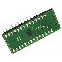
Daughter Board
Manufacturer
BOSCH
Datasheet
1.BMA140-SHUTL.pdf
(24 pages)
Specifications of BMA140-0330SB000A
Silicon Manufacturer
Bosch
Application Sub Type
Accelerometer - Three-Axis
Kit Application Type
Sensing - Motion / Vibration / Shock
Silicon Core Number
BMA140
Kit Contents
Board


BMA140
Bosch Sensortec
Data sheet
Triaxial, analog acceleration sensor
The BMA140 in general
The BMA140 is a triaxial low-g acceleration sensor for consumer market applications, available
2
in a standard SMD LGA package with a footprint of 3x3mm
and a height of only 0.9mm. It
allows measurements of static as well as dynamic accelerations. Due to its three perpendicular
axes it gives the absolute orientation in a gravity field and enables free fall detection. As all
other Bosch inertial sensors, the BMA140 is a two-chip arrangement, which combines an
application-specific integrated circuit (ASIC) with a three-channel silicon accelerometer, to form
a true micro electro mechanical system (MEMS).
The ASIC evaluates the output of the acceleration-sensing element, corresponding to the
differential capacitance principle. The underlying MEMS technology processes have proven
their capability according to the strictest automotive standards in more than 100 million Bosch
inertial sensors a year so far.
The BMA140 provides 3 parallel analog output signals in a ±4g acceleration range. All
acceleration signals are permanently available on 3 independent analog pads through 33kΩ
resistors on each pad. This allows the user defining the signal bandwidth by the mean of
external capacitors connected between each channel output and ground. Additional to the
parallel X, Y and Z output signals there is the option to multiplex any axis to one supplementary
output pin in a freely customized manner. This allows the user to connect the triaxial BMA140 to
an economical single channel AD converter without loss of axis information.
st
For each axis, an independent analog 1.5 kHz 1
-order low-pass filter is included to provide
preconditioning of the measured acceleration signal. The corner frequency of this filter can
easily be customized. Additional signal preconditioning steps are performed by a digital to
analog converter for offset and gain correction purposes with a subsequent signal amplification.
The output signals are ratiometric. In the ±4g acceleration range the sensor is offering a
sensitivity of 300mV/g at 3.0 V supply voltage (V
/ 10) and 220µg/√Hz as a typical noise level.
DD
The typical current consumption is 200µA in operation. Furthermore, the sensor can be
switched into a standby mode via supplementary selection pins. In standby mode the sensor
module features an ultra low current consumption of typically 0.7 µA. The return from standby
mode to full performance conditions is performed in less than 1ms wake up time.
The BMA140 sensor module is ready to use due to test and calibration at factory level. All
calibration parameters, e.g. for offset and sensitivity, are stored in an internal EEPROM. The
sensor also features full self-test capability for all three axes. It is activated via a single self test
activation pin which results in a physical deflection of the seismic mass in the sensing element
due to electrostatic forces. Thus, it provides contact and functional testing of the complete
signal evaluation path including the MEMS acceleration-sensing element and the evaluation
ASIC.
Rev. 1.1
Page 3
04 April 2008
© Bosch Sensortec GmbH reserves all rights even in the event of industrial property rights. We reserve all rights of disposal such
as copying and passing on to third parties. BOSCH and the symbol are registered trademarks of Robert Bosch GmbH, Germany.
Note: Specifications within this document are subject to change without notice.
Related parts for BMA140-0330SB000A
Image
Part Number
Description
Manufacturer
Datasheet
Request
R

Part Number:
Description:
BMA140 DAUGHTERCARD FOR DEV KIT
Manufacturer:
Bosch Sensortec
Datasheet:

Part Number:
Description:
3-AXIS ACCELEROMETER ANALOG I/F
Manufacturer:
Bosch Sensortec
Datasheet:

Part Number:
Description:
COLOR 1/3CCD BOSCH CAMERA . 480TVL 0.1LUX LENS NOT INCL
Manufacturer:
BOSCH