SI9166DB-K Vishay, SI9166DB-K Datasheet - Page 2
SI9166DB-K
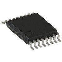
Manufacturer Part Number
SI9166DB-K
Description
Pulse Width Modulation (PWM) Controller IC
Manufacturer
Vishay
Datasheet
1.SI9166BQ-T1.pdf
(9 pages)
Specifications of SI9166DB-K
Silicon Manufacturer
Vishay
Application Sub Type
Programmable Topology Controller
Kit Application Type
Power Management - Voltage Regulator
Silicon Core Number
SI9166
Kit Contents
Board
Lead Free Status / RoHS Status
Contains lead / RoHS non-compliant


Si9166
Vishay Siliconix
ABSOLUTE MAXIMUM RATINGS
Voltages Referenced to GND
V
MODE, PWM/PSM, SYNC, SD, V
COMP, FB
V
PGND
Voltages Referenced to PGND
V
DH, DL
Stresses beyond those listed under “Absolute Maximum Ratings” may cause permanent damage to the device. These are stress ratings only, and functional operation
of the device at these or any other conditions beyond those indicated in the operational sections of the specifications is not implied. Exposure to absolute maximum rating
conditions for extended periods may affect device reliability.
RECOMMENDED OPERATING CONDITIONS
Voltages Referenced to AGND
V
MODE, PWM/PSM, SYNC, SD
Voltages Referenced to PGND
V
www.vishay.com
2
SPECIFICATIONS
Reference
Output Voltage
Output Voltage
Load Regulation
Power Supply Rejection
UVLO
Under Voltage Lockout (turn-on)
Hysteresis
Soft-Start Tim
SS time
Mode
Logic High
Logic Low
Input Current
SD, SYNC, PWM/PSM
Logic High
Logic Low
Input Current
DD
O
S.
DD
S
. . . . . . . . . . . . . . . . . . . . . . . . . . . . . . . . . . . . . . . . . . . .
. . . . . . . . . . . . . . . . . . . . . . . . . . . . . . . . . . . . . . . . . . . . . . . . . . . .
. . . . . . . . . . . . . . . . . . . . . . . . . . . . . . . . . . . . . . . . . . . . . . . . . . . . . . . .
. . . . . . . . . . . . . . . . . . . . . . . . . . . . . . . . . . . . . . . . . . . . . . . . . . . . . . . .
. . . . . . . . . . . . . . . . . . . . . . . . . . . . . . . . . . . . . . . . . . . . . . . . . . .
. . . . . . . . . . . . . . . . . . . . . . . . . . . . . . . . . . . . . . . . . . . . . . . . . . .
. . . . . . . . . . . . . . . . . . . . . . . . . . . . . . . . . . . . . . . .
Parameter
. . . . . . . . . . . . . . . . . . . . . . . . . . . . . . . . . . . .
. . . . . . . . . . . . . . . . . . . . . . . . . . . .
REF
, R
OSC
Symbol
V
DV
UVLOLH
V
V
P
V
V
V
tss
V
V
SRR
HYS
REF
REF
I
I
REF
IH
L
IH
L
IL
IL
−0.3 V to V
−0.3 V to V
−0.3 V to V
Unless Otherwise Specified
Unless Otherwise Specified
V
2.7 V to 6 V
2.7 V to 6 V
DD
DD
0 V to V
S
S
2.7 V v V
"0.3 V
= 3.3 V, −500 µA < I
Test Conditions
+ 0.3 V
+ 0.3 V
+ 0.3 V
V
I
REF
6.5 V
6.5 V
UVLOLH
DD
I
= 0, T
REF
DD
− V
= 0A
A
, V
UVLOHL
= 25°C
S
v 6 V
Peak Output Current (DH, DL)
Storage Temperature
Operating Junction Temperature
Power Dissipation (Package)
16-Pin TSSOP (Q Suffix)
Thermal Impedance (q
16-Pin TSSOP
Notes
a.
b.
F
R
V
osc
osc
REF
REF
Device mounted with all leads soldered or welded to PC board.
Derate 7.4 mW/
. . . . . . . . . . . . . . . . . . . . . . . . . . . . . . . . . . . . . . . . . . . .
. . . . . . . . . . . . . . . . . . . . . . . . . . . . . . . . . . . . . . . . . . . . .
Capacitor
<0
. . . . . . . . . . . . . . . . . . . . . . . . . . . . . . . . . . . . . . . . . . .
. . . . . . . . . . . . . . . . . . . . . . . . . . . . . . . . . . . . . . . . . . . . .
_
0.7 V
Min
1.268
1.280
C above 25
. . . . . . . . . . . . . . . . . . . . . . . . . . . . . . . .
−1.0
−1.0
JA
2.3
2.4
b
)
DD
a
. . . . . . . . . . . . . . . . . . . . . . . . . . . . . . . . . .
a
. . . . . . . . . . . . . . . . . . . . . . . . . . . . . . . . .
_
. . . . . . . . . . . . . . . . . . . . . . . . . . . . . .
C.
Limits
Typ
1.3
1.3
2.4
0.1
60
3
6
b
S-40701—Rev. C, 19-Apr-04
Document Number: 70847
Max
0.3 V
1.332
1.320
2.5
1.0
0.8
1.0
200 kHz to 2 MHz
DD
25 kW to 300 kW
−65_C to 150_C
a
135_C/W
925 mW
Unit
150_C
0.1 mF
mV
mS
dB
mA
mA
1.5 A
V
V
V
V
V
V
V
V
Related parts for SI9166DB-K
Image
Part Number
Description
Manufacturer
Datasheet
Request
R

Part Number:
Description:
High Frequency Programmable Topology Controller
Manufacturer:
Vishay
Datasheet:
Part Number:
Description:
357-036-542-201 CARDEDGE 36POS DL .156 BLK LOPRO
Manufacturer:
Vishay
Datasheet:
Part Number:
Description:
357-036-542-201 CARDEDGE 36POS DL .156 BLK LOPRO
Manufacturer:
Vishay
Datasheet:
Part Number:
Description:
357-036-542-201 CARDEDGE 36POS DL .156 BLK LOPRO
Manufacturer:
Vishay
Datasheet:
Part Number:
Description:
357-036-542-201 CARDEDGE 36POS DL .156 BLK LOPRO
Manufacturer:
Vishay
Datasheet:
Part Number:
Description:
357-036-542-201 CARDEDGE 36POS DL .156 BLK LOPRO
Manufacturer:
Vishay
Datasheet:
Part Number:
Description:
357-036-542-201 CARDEDGE 36POS DL .156 BLK LOPRO
Manufacturer:
Vishay
Datasheet:
Part Number:
Description:
357-036-542-201 CARDEDGE 36POS DL .156 BLK LOPRO
Manufacturer:
Vishay
Datasheet:
Part Number:
Description:
357-036-542-201 CARDEDGE 36POS DL .156 BLK LOPRO
Manufacturer:
Vishay
Datasheet:
Part Number:
Description:
357-036-542-201 CARDEDGE 36POS DL .156 BLK LOPRO
Manufacturer:
Vishay
Datasheet:
Part Number:
Description:
357-036-542-201 CARDEDGE 36POS DL .156 BLK LOPRO
Manufacturer:
Vishay
Datasheet:
Part Number:
Description:
357-036-542-201 CARDEDGE 36POS DL .156 BLK LOPRO
Manufacturer:
Vishay
Datasheet:
Part Number:
Description:
357-036-542-201 CARDEDGE 36POS DL .156 BLK LOPRO
Manufacturer:
Vishay
Datasheet:
Part Number:
Description:
357-036-542-201 CARDEDGE 36POS DL .156 BLK LOPRO
Manufacturer:
Vishay
Datasheet:
Part Number:
Description:
357-036-542-201 CARDEDGE 36POS DL .156 BLK LOPRO
Manufacturer:
Vishay
Datasheet: