LPC1758-SK EMBEST, LPC1758-SK Datasheet
LPC1758-SK
Specifications of LPC1758-SK


Related parts for LPC1758-SK


LPC1758-SK Summary of contents
Page 1
... EM-LPC1700 Evaluation Board User Manual V1.2 EMBEST CO., LIMITED Address:Room 509, Luohu Science & Technology Building, #85 Taining Road, Shenzhen, Guangdong, China 518020 Telephone: 0086-755-25621715 or 25635626 ext. 1715 Fax: 0086-755-25616057 E-mail: sales.en@embedinfo.com || support.en@embedinfo.com Website: http://www.embedinfo.com/en www.embedinfo.com/en 1/21 ...
Page 2
...............................................................3 HAPTER VERVIEW 1.1 Product List includes .....................................................4 1.2 Getting Start................................................................4 1.3 Jumpers ...................................................................... M-LPC1700 H HAPTER 2.1 Board Overview............................................................6 2.2 Jumpers Setting ...........................................................7 2.3 EM-LPC1700 Block Diagram ...........................................7 2.4 Power Supply ...............................................................8 2.5 Clock ...
Page 3
... Note: EM-LPC1700 Evaluation Board is available in three variants: the LPC1758, LPC1766 and LPC1768. • The LPC1758 board (Order# P758): Processor is populated with the NXP LPC1758 microcontroller, 512KB Flash memory, 80 pins, 100MHz. • The LPC1766 (Order# P766): Processor is populated with the NXP LPC1766 microcontroller, 256KB Flash memory, 100 pins, 100MHz. • ...
Page 4
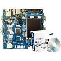
Product List includes One EM-LPC1700 board 2.4 inches TFT LCD(240*320) One Cross-serial line One USB A-B cable One Crossover network cable One EM-LPC1700 CD 1.2 Getting Start Power EM-LPC1700 is supplied power by using a standard USB connector. • ...
Page 5
Jumpers Table1. Jumpers Setting jumper state (JP6 ENET Connect P2.8, make CAN2 or Ethernet available E/C D- (JP9) HOST D+ (JP8) HOST SPK (JP16 VBAT (JP1) ON VDDIO (JP15) ON VDDREG(JP14) ON VBUS (JP12) ON ...
Page 6
Chapter 2 EM-LPC1700 Hardware Specification 2.1 Board Overview Table 2. A List of Hardware Interfaces J1 USART DB9 male connector COM1 J2 USART DB9 male connector COM0 J3 RJ45 network interface J4 Cortex Debug J5 CAN1 DB9 male connector J6 ...
Page 7
U5 DM83848 U6/7 TJA1040 U9 ISP1301 2.2 Jumpers Setting Designation Description JP6 CAN JP8/9 USB JP10 USB JP11 USB/Network 2.3 EM-LPC1700 Block Diagram www.embedinfo.com/en Setting Option Setting Description 1-2 Select CAN Controller 2-3 Select Ethernet Controller Above USB OTG Mode ...
Page 8
Power Supply EM-LPC1700 evaluation board supports two power supply modes; you can select one of the two power supply modes below through JP12 configuration. 1) Supply 5V DC through power jack (JP11) on the board. 2) Supply power through ...
Page 9
UART1 RS232 DB9 connecter signal definition: Pin No UART1_RXD 3 UART1_TXD 4 5 2.8 SD Card Interface STM32 evaluation board has SD card connector and supports SD card read/write operation. SD card and EM-LPC1700 interface connection signal as ...
Page 10
CAN Connector EM-LPC1700 evaluation board use SN65HVD230 (U10) as CAN driver chip, CAN connecter adopts DB9 to connect wires, here pin2 provides CANL signal and pin7 provides CANH signal. These pins are connected to CAN driver chip SN65HVD230. CAN ...
Page 11
... Location of source code: LCD Corresponding chip manual: Datasheet\LCD corresponding\ MR024-9325-51P-B.pdf Steps: Download LCD_Blinky.hex to the FLASH of MCU Testing phenomenon: D2-D9 blink, and LCD displays the LOGO and related words of Embest Co. (3) UART Testing Image file: UART.hex Location of source code: UART Corresponding chip manual: Datasheet\[processor].pdf Steps: 1) Download UART ...
Page 12
Steps: Download rtc.hex to the FLASH of MCU Testing phenomenon: Examine the corresponding changes which the RTC related register bring about (5) DAC SPK Testing Image file: DAC_Test.hex Location of source code: DAC Corresponding chip manual: Datasheet\[processor].pdf Steps: Download DAC_Test.hex ...
Page 13
BUTTON, and then it appears the following forms which show the change of AD value and Joystick’s button value (9) SD card Testing (RL-ARM holder) Image file: SD_file.hex Location of source code: SD_file Corresponding chip manual: Steps: Download SD_file.hex to ...
Page 14
Chapter 3 Software development and examples 3.1 MDK Introduction RealView MDK Development Suite is the latest software development tool released by ARM Corporation for ARM MCU embedded processors. It integrates the most advanced technology in this industry, including μVision3 IDE ...
Page 15
Click Flash/Download to download the image as follows: Or click the shortcut icon: to download the image. Click to download procedure 5) After download, execute Debug/Start/Stop Debug Session(Ctrl+F5) to debug as follows: or click shortcut con: to start debug. ...
Page 16
You can make use of the debug shortcut icon in the window to execute debug process, the icon as follows: www.embedinfo.com/en 16/21 ...
Page 17
Appendix A: IO Assignment on EM-LPC1700 Evaluation Board Pin TQFP100 1 TD0/SW0 2 TDI 3 TMS/SWDIO 4 TRST 5 TCK/SWDCLK 6 P0.26 7 P0.25 8 P0.24 9 P0.22 10 VDDA 11 VSSA 12 VREFP RSTOUT 15 VREFN ...
Page 18
P1.30 22 XTAL1 23 XTAL2 24 P0.28 25 P0.27 26 P3.26 27 P3.25 28 VDD(3V3)_3 29 P0.29 30 P0.30 31 VSS_0 32 P1.18 33 P1.19 34 P1.20 35 P1.21 36 P1.22 37 P1.23 38 P1.24 39 P1.25 40 P1.26 ...
Page 19
P1.29 46 P0.0 47 P0.1 48 P0.10 49 P0.11 50 P2.13 51 P2.12 52 P2.11 53 P2.10 54 VDD(3V3)_2 55 VSS_2 56 P0.22 57 P0.21 58 P0.20 59 P0.19 60 P0.18 61 P0.17 62 P0.15 63 P0.16 64 P2.9 ...
Page 20
P2.4 70 P2.3 71 VDD(3V3)_1 72 VSS_3 73 P2.2 74 P2.1 75 P2.0 76 P0.9 77 P0.8 78 P0.7 79 P0.6 80 P0.5 81 P0.4 82 P4.28 83 VSS_4 VDD(REG)(3V3 P4.29 86 P1.17 87 P1.16 88 ...
Page 21
P1.4 94 P1.1 95 P1.0 96 VDD(3V3)_0 97 VSS_5 98 P0.2 99 P0.3 100 RTCK www.embedinfo.com/en I/O I/O I/O JTAG Ethernet Ethernet Ethernet 3.3V GND UART0 UART0 JTAG_RTCK 21/21 ...