CME-12B32 AXIOM, CME-12B32 Datasheet
CME-12B32
Specifications of CME-12B32


Related parts for CME-12B32


CME-12B32 Summary of contents
Page 1
... Axiom Manufacturing, 1998 717 Lingco Dr., Suite 202 Richardson, TX 75081 972) 994-9676 FAX (972) 994-9170 email: gary@axman.com web: http://www.axman.com CME12B32 Development Board ...
Page 2
... DEVELOPMENT PHILOSOPHY ..................................................................3 TUTORIAL.....................................................................................................4 U DBUG12..................................................................................................... 4 SING Example Program................................................................................................ 4 Writing to Internal Flash Memory using AX12..................................................... 5 U BDM..................................................................................................... 6 SING THE Example Program................................................................................................ 6 Writing to Internal Flash Memory using the BDM ............................................... 7 CME12B32 BOARD LAYOUT ......................................................................8 MEMORY MAP..............................................................................................9 JUMPERS ................................................................................................... ISCELLANEOUS UMPERS MOD J .................................................................................................... 10 UMPERS MEM-SEL J UMPERS EVU J ...
Page 3
... DEVELOPMENT PHILOSOPHY Software development on the CME12B32 can be performed using either the DBUG12 monitor utility installed in EPROM (sockets U6/U7), the DBUG12 monitor programmed into the internal Flash EPROM or a Background Debug Module (BDM) connected to the DEBUG connector. Any of these tools can be used to assist in creating and debugging your program that is stored in either internal RAM ($800-$C00) or external RAM (U4/U5 see Memory Map) ...
Page 4
... This tutorial will walk you thru the complete development cycle of a very simple program. This should help you get started with the specifics of the CME12B32 development process. Be sure to read the rest of this manual as well as the documentation on the disk if you need further information. ...
Page 5
Writing to Internal Flash Memory using AX12 When you’re finished with program development, you will probably want to write your program to Internal Flash Memory so that it executes automatically when you apply power to the board. The following procedure ...
Page 6
... It's a good idea to set this word in your application program. Example Program Included on CME12B32 software disk is a program called HELLO3.ASM. This is a simple program that outputs a text string to the HC12 serial port. It can be modified and assembled using the included free assembler, but for now just load it into the BDM by selecting File / Load S19 or Hex from the menu ...
Page 7
... Upper Memory. Enable program boot area if you are changing the reset or other interrupt vectors, then select "Start to Program" button. After programming is complete, you can remove the BDM module and your program should start whenever the CME12B32 board is powered on. WARNING : As a safety precaution, ALWAYS remove the VPP_EN jumper after programming to protect the micro from being accidentally erased or damaged. ...
Page 8
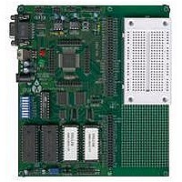
... CME12B32 BOARD LAYOUT 8 ...
Page 9
MEMORY MAP Following is the DEFAULT memory map for this development board: 0000 01FF CS0 – CS6 Chip Selects 0200 – 026F CS7, LCD Ports 0270 – 027F unused 0280 – 03FF 0400 07FF 0800 0BFF 0C00 0CFF 0D00 0FFF ...
Page 10
JUMPERS Miscellaneous Jumpers IN = U4/5 (SRAM) write enabled JP1 OUT = U4/5 (SRAM) write disabled (write protect External bus/memory devices enabled (U4/5/6 Expanded Mode) JP2 OUT = External Memory disabled JP2 must be IN for ...
Page 11
PORTS and CONNECTORS BUS_PORT GND 1 2 D11 D10 3 4 D12 D13 D14 D15 A10 A11 17 18 ...
Page 12
MCU_PORT2 VRH 1 2 VRL 3 4 +5v GND 5 6 PAD0 PAD1 PAD2 7 8 PAD3 9 10 PAD5 PAD4 PAD6 11 12 PAD7 + GND PS0 / RXD 15 16 PS1 / TXD PS2 17 18 ...
Page 13
... The DEBUG port pin header compatible in pinout with the Motorola Background Debug Mode (BDM) Pod. This allows the connection of a background debugger for software development, programming and debugging in real-time, since the BDM control logic does not reside in the CPU. A Background Debug Module is available from the manufacturer. Contact Axiom Manufacturing for more information. BGND ...
Page 14
... TROUBLESHOOTING The CME12B32 board is fully tested and operational before shipping fails to function properly, inspect the board for obvious physical damage first. Ensure that all socketed IC devices are properly seated in the their sockets. The most common problems are improperly configured communications parameters and attempting to use the wrong COM port (on the PC AND on the development board) ...
Page 15
Tips and Suggestions Following are a number of tips, suggestions and answers to common questions that will solve most problems users have with the AX12 development system. This information is also available in the AX12 program under Troubleshooting, which will ...