EB194 MATRIX, EB194 Datasheet - Page 10
EB194
Manufacturer Part Number
EB194
Description
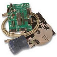
MULTI PROGRAMMER KIT, AVR, ATMEL
Manufacturer
MATRIX
Datasheet
1.EB194.pdf
(14 pages)
Specifications of EB194
Mcu Supported Families
Atmel AVR
Programmer Type
Multiprogrammer
Development Tool Type
AVR Multiprogrammer
Tool / Board Application
Programming / Developing
Tool / Board
RoHS Compliant
Ic Product Type
In-Circuit Programmer
Features
E-Blocks Compatible, Low Cost, Used As A Programmer And As A Development Board, 4 Full I/O Ports
Rohs Compliant
Yes


Matrix Multimedia Atmel AVR® Board
EB19430
programming. This removes the link to Port B, so pins RB5, RB6 and RB7 are only used for
programming.
It is possible to get 100% clean signals on RB5, RB6 and RB7 by placing the 3-way jumper link in
the side opposite to that labelled “default” on J9, J10 and J11. Please note that the AVR® devices
can NOT be programmed when in this state – this state is only recommended if problems with
attachments in Port B occur.
Programming - Software
The CD ROM includes a range of development tools including an Integrated Development
Environment for code writing in assembly and debugging, a professional C compiler, and the ISP
programming software.
DIL Sockets and I / O Ports
The slave AVR® DIL sockets are wired in parallel (see table of connections below) and the ports
are fed out to 4 D-type sockets grouped in ports. These signals are also available on a 40-way
header for expansion purposes. Some of the ports will be inactive. This reflects the pin outs of the
various AVR® devices themselves. For example, the AT90S1200 only has Port B and Port D,
therefore Port A and Port C are inactive. Please refer to device datasheets for availability of port
outputs on each device.
NOTE – Only insert ONE Atmel AVR® device at a time!
Reset Push Button
PB1 provides a reset by pulling the /RESET pin low. PB1 is pulled normally high through a resistor
so that the device will not be reset during normal operation. The programming software has
control over the reset line during programming.
Frequency Selection
By default the board is fitted with a 11.0592 MHz crystal. The crystal fits into a small socket, which
allows the crystal to be easily changed. These frequencies are chosen as they divide down by
AVR® pre-scalers to give suitable frequencies for clock systems and for facilitating serial
communication using standard baud rates.
USB circuitry
In the future there may be a possibility of this device being USB compatible. The PCB has been
manufactured with the circuitry on board to enable quick development.
Note this circuitry is not suppose to be populated
Copyright © 2004 Matrix Multimedia Limited
Page 10
Related parts for EB194
Image
Part Number
Description
Manufacturer
Datasheet
Request
R


Part Number:
Description:
MATRIX CARD FOR HI-LO PROG
Manufacturer:
Cypress Semiconductor Corp
Part Number:
Description:
MATRIX CARD FOR HI-LO PROG
Manufacturer:
Cypress Semiconductor Corp
Datasheet:
Part Number:
Description:
MATRIX CARD FOR HI-LO PROG
Manufacturer:
Cypress Semiconductor Corp
Datasheet:
Part Number:
Description:
MATRIX CARD FOR HI-LO PROG
Manufacturer:
Cypress Semiconductor Corp
Datasheet:
Part Number:
Description:
MATRIX CARD FOR HI-LO PROG
Manufacturer:
Cypress Semiconductor Corp
Part Number:
Description:
MATRIX CARD FOR HI-LO PROG
Manufacturer:
Cypress Semiconductor Corp
Part Number:
Description:
MATRIX CARD FOR HI-LO PROG
Manufacturer:
Cypress Semiconductor Corp
Datasheet:
Part Number:
Description:
MATRIX CARD FOR HI-LO PROG
Manufacturer:
Cypress Semiconductor Corp

Part Number:
Description:
Color Video Chrominance Signal Processing Circuit
Manufacturer:
Matrix Orbital.
Datasheet:
Part Number:
Description:
Recording Video Signal Processing Circuit
Manufacturer:
Matrix Orbital.
Datasheet:
Part Number:
Description:
Driver Circuit
Manufacturer:
Matrix Orbital.
Datasheet: