GSM9000 RF Solutions, GSM9000 Datasheet - Page 16
GSM9000
Manufacturer Part Number
GSM9000
Description
Tri-band Wireless Module Supporting Both GSM And GPRS
Manufacturer
RF Solutions
Datasheet
1.GSM9000-CON.pdf
(29 pages)
Specifications of GSM9000
No. Of Channels
2
Frequency Rf
1.8GHz
Module Interface
Serial, UART
Kit Contents
Module Board Docs
Tool / Board Applications
Wireless Connectivity-ZigBee, RF, Infrared, USB
Lead Free Status / RoHS Status
Lead free / RoHS Compliant


Product Description
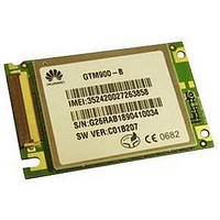
Huawei GTM900 GSM/GPRS Wireless Module
2.2.2 Design of Signal Connector
2.3 Antenna Interface
The signals at the serial interfaces are named with PC
Communications Equipment).
The signal connector assembled on GTM900 is a type of 40-pin FPC with the cross-pin
distance of 0.5 mm and the cross-wire distance of 0.5 mm. The connector employs the
single-row and surface-mounted structure with bend pins and the cable-locking device.
It is type Hirose FH12-40S-0.5SH. See Figure 2-1 for its appearance.
Figure 2-1 Appearance of signal connector
GTM900 uses a GSC connector to establish the RF connection to the relevant terminal.
The external antenna connects to the connector through a cable. The connector with
35
36
37
38
39
40
No.
Note:
EAR+
EAR-
MIC+
MIC-
AUXI+
AUXI-
Signal
Huawei Technologies Proprietary
O
O
I
I
I
I
I/O
--
--
--
--
--
--
Interface
level
2-3
Receiver audio output signals+
Receiver audio output signals–
Receiver audio input signals+
Receiver audio input signals–
Hands-free audio input signals+
Hands-free audio input signals–
Function
Chapter 2 Interface Signals
as the DCE(Data
--
--
--
--
--
--
Note
Related parts for GSM9000
Image
Part Number
Description
Manufacturer
Datasheet
Request
R

Part Number:
Description:
RF SOLUTIONS FOR TRANSPORTATION
Manufacturer:
Skyworks Solutions Inc


Part Number:
Description:
RF Switch SPDT 0MHz to 2GHz 27dB 8-Pin SOIC T/R
Manufacturer:
M/A-Com Technology Solutions
Datasheet:
Part Number:
Description:
RF Switch SPST 500MHz to 2GHz 40dB 8-Pin SOIC T/R
Manufacturer:
M/A-Com Technology Solutions
Datasheet:
Part Number:
Description:
RF Switch SPDT 100MHz to 4GHz 14dB 6-Pin SOT-6
Manufacturer:
Skyworks Solutions Inc
Datasheet:
Part Number:
Description:
RF Switch SPST 500MHz to 2.5GHz 10dB 6-Pin SOT-6
Manufacturer:
Skyworks Solutions Inc
Part Number:
Description:
RF Amp Module Single Power Amp 1.91GHz 4.2V 10-Pin MCM
Manufacturer:
Skyworks Solutions Inc
Datasheet:
Part Number:
Description:
RF Amp Chip Single Power Amp 2.5GHz 4.5V 16-Pin QFN T/R
Manufacturer:
Skyworks Solutions Inc
Datasheet:

Part Number:
Description:
IC ENCODER TRANSMITTER RF 8DIP
Manufacturer:
RF Solutions
Datasheet:

Part Number:
Description:
IC DECODER RECEIVER RF 18DIP
Manufacturer:
RF Solutions
Datasheet:

Part Number:
Description:
IC ENCODER 3 DGTL I/O SOT23-6
Manufacturer:
RF Solutions
Datasheet:

Part Number:
Description:
IC ENCODER 3 DGTL I/O 8-PDIP
Manufacturer:
RF Solutions
Datasheet:

Part Number:
Description:
IC DECODER 3 DGTL I/O 8-PDIP
Manufacturer:
RF Solutions
Datasheet: