PT07C14-18P Amphenol Industrial Operations, PT07C14-18P Datasheet - Page 51
PT07C14-18P
Manufacturer Part Number
PT07C14-18P
Description
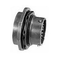
PT07C SERIES (MS3114) PRESSURIZED JAM NUT RECEPTACLES, STRAIGHT BODY STYLE, SOLDER TERMINATION, 14 SHELL SIZE, 14-18 INSERT ARRANGEMENT, PLUG GENDER, 18 CONTACTS
Manufacturer
Amphenol Industrial Operations
Datasheet
1.PT06SE-14-19S-SR.pdf
(80 pages)
Specifications of PT07C14-18P
Gender
Receptacle
Contact Gender
Pin
Connector Mounting
Panel
Connector Shell Size
14
Insert Arrangement
14-18
No. Of Contacts
18
Contact Termination
Solder
Contact Material
Copper


PT-CE, SP-CE
how to order
PT-CE, SP-CE
To more easily illustrate ordering procedure, part number
PT00CE-20-41PW (SR) is shown as follows:
See code below:
1. Connector Type
2. Shell Style
3. Service Class
4. Shell Size
5. Insert Arrangement
6. Contacts
7. Insert Rotation
8. “(SR)” designates strain relief clamp.
* This connector style is sometimes referred to as a cable connecting “plug”.
For ordering Miniature Breakaway PT-CE Crimp connectors see page 48.
PT
It does, however, mate with either a straight or 90 degree plug.
1
“PT” designates standard electrically conductive olive drab cadmium plated
bayonet lock connector with crimp contacts
“SP” designates electrically non-conductive, hard anodic coated bayonet
lock connector with large flange and mounting holes for back panel mount-
ing, and crimp contacts.
“00”
“01”
“02”
“06”
“07”
“08”
“CE”
“CP”
Both of the above are Amphenol
26482, Series 1 crimp contact connector and offer 7 lbs. contact retention
for size 20 contacts; 9 lbs for size 16 contacts.
“20” designates shell size. Shell sizes 6 through 24 available.
Refer to pages 4-11 for insert availability.
“20 – 41” designates insert arrangement. (The number following the
hyphen is the number only that is used in the part number).
“P” designates pin contacts.
“S” designates socket contacts.
Refer to page 7.
“W”, “X”, “Y”, “Z” designate that insert is rotated in its shell from the “nor-
mal” position. No letter required for normal (no rotation) position.
Indicate optional finishes as follows:
(003)
(005)
(014)
(023)
(024)
(025)
(027)
(424)
(466)
(470)
(476)
00
2
designates wall mounting receptacle
designates cable connecting receptacle*
designates box mounting receptacle
designates straight plug
designates jam nut receptacle
designates 90° plug
designates environmental crimp
designates potted type crimp
olive drab cadmium plate (standard on “PT”)
anodic coating - Alumilite
olive drab cadmium plate over nickel
electroless nickel
olive drab zinc cobalt plating
non-conductive black zinc cobalt plating
conductive black zinc cobalt plating
electroless nickel finish with strain relief
olive drab zinc cobalt plating with strain relief
non-conductive black zinc cobalt plating with strain relief
conductive black zinc cobalt with strain relief
CE – 20 – 41
3
4
5
P
6
®
®
(standard on “SP”)
proprietary versions of the MIL-C-
W
7
(SR)
8
49
Related parts for PT07C14-18P
Image
Part Number
Description
Manufacturer
Datasheet
Request
R

Part Number:
Description:
JAM NUT CONN RCPT, SIZE 14, 12POS, PANEL
Manufacturer:
Amphenol Industrial Operations
Datasheet:
Part Number:
Description:
JAM NUT CONN RCPT, SIZE 14, 12POS, PANEL
Manufacturer:
Amphenol Industrial Operations
Datasheet:
Part Number:
Description:
JAM NUT CONN RCPT, SIZE 14, 15POS, PANEL
Manufacturer:
Amphenol Industrial Operations
Datasheet:
Part Number:
Description:
JAM NUT CONN RCPT, SIZE 14, 15POS, PANEL
Manufacturer:
Amphenol Industrial Operations
Datasheet:
Part Number:
Description:
JAM NUT CONN RCPT, SIZE 14, 19POS, PANEL
Manufacturer:
Amphenol Industrial Operations
Datasheet:

Part Number:
Description:
JAM NUT CONN, RCPT, SIZE 9, 6POS, PANEL
Manufacturer:
Amphenol Industrial Operations
Datasheet:

Part Number:
Description:
PT 41C 41#20 PIN RECP
Manufacturer:
Amphenol Industrial Operations
Part Number:
Description:
PT 41C 41#20 SKT RECP
Manufacturer:
Amphenol Industrial Operations