09 69 200 9050 HARTING, 09 69 200 9050 Datasheet
09 69 200 9050
Specifications of 09 69 200 9050


Related parts for 09 69 200 9050


09 69 200 9050 Summary of contents
Page 1
... D-Sub – M D-Sub – Mixed subminiature D connectors D-Sub mixed connector system – general information . . . . . . . . . . . . . . . . . . . Contact arrangements . . . . . . . . . . . . . . . . . . . . . . . . . . . . . . . . . . . . . . . . . . . . Connectors for pcb applications – general information . . . . . . . . . . . . . . . . . . . Connectors for cable applications – general information . . . . . . . . . . . . . . . . . . Technical characteristics for shells . . . . . . . . . . . . . . . . . . . . . . . . . . . . . . . . . . ...
Page 2
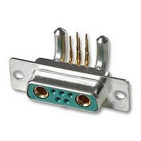
... D-Sub mixed connector system HARTINGs’ mixed D-Sub range brings the advantage of an industry standard I/O inter- connect product with the possibility to customise for any application. The range is designed around the standard D-Sub shell sizes with the possibility to have a blend of contacts such as signals with coaxial, power, high voltage or pneumatic contacts ...
Page 3
... Example: 13W3 stands for 13 contacts in total with 10 signal contacts and 3 special contacts. Shell size 2W2C 1 5W1 1 3W3 2 3W3C 2 7W2 2 11W1 2 5W5 3 9W4 3 13W3 3 17W2 3 21W1 3 Shell size 7W7 4 8W8 4 13W6 4 21WA4 4 25W3 4 27W2 4 24W7 5 36W4 5 Note: for any other layout please consult your HARTING representative ...
Page 4
... D-Sub Connectors for pcb applications – general information The range of pcb connectors available at HARTING is summarised in the table under. For each of the basic connector versions, the available contact styles are documented with termination process, pitch, plating, rating for power contacts and impedance for coaxial contact etc..., as well as the accessory configuration. ...
Page 5
... D-Sub Connectors for cable applications – general information Two termination processes are available: crimp or solder Shell Crimp termination Signal contacts For wire gauge: AWG 20-24 or 26-28 ● Plating: 0.76 µm or 0.2 µm Au over Ni ● Crimp Rating: 10, 20, 30 ● Plating: 0.76 µm or 0.2 µm Au over Ni ● ...
Page 6
... D-Sub mixed connectors Number of contacts Approvals Working current Temperature range The higher temperature limit includes the ambient and heating effect of the contacts under load Materials Mouldings Metal shell Technical characteristics for special contacts see page 04.21 Technical characteristics for shells 11, 13, 17, ...
Page 7
... D-Sub DIN 41 652 T1 Number of contacts 7--27 Mixed shells with pre-mounted signal solder cup contacts Identification Male connectors Female connectors 1) Explanations see page 04.03 S4: ≥ 0.76 µ No. of contacts 1) male connectors Performance level 3 S4 7W2 09 69 211 7072 09 69 211 5072 17W2 ...
Page 8
... D-Sub DIN 41 652 T1 Number of contacts 9--25 Mixed shells with pre-mounted signal solder cup contacts Identification Male connectors Explanations see page 04.03 S4: ≥ 0.76 µ Board drillings see pages 04.30 ff No. of contacts 1) male connectors Performance level 3 S4 9W4 09 69 311 7094 09 69 311 5094 ...
Page 9
... D-Sub DIN 41 652 T1 Number of contacts 9--25 Mixed shells with pre-mounted signal solder cup contacts Identification Female connectors Board drillings see pages 04.30 ff Drawing 13W3, 25W3 Dimensions in mm 9W4 Solder cup termination for AWG 20 (0.5 mm²) Solder cup termination for AWG 20 (0.5 mm²) ...
Page 10
... D-Sub DIN 41 652 T1 Number of contacts 5--21 Mixed shells with pre-mounted signal solder cup contacts Identification Male connectors Female connectors Explanations see page 04.03 S4: ≥ 0.76 µ Board drillings see pages 04.30 ff No. of contacts 1) male connectors Performance level 3 S4 5W1 09 69 111 7051 ...
Page 11
... D-Sub DIN 41 652 T1 Number of contacts 13 Mixed shells with pre-mounted signal solder cup contacts Identification Male connectors Female connectors 1) Explanations see page 04.03 S4: ≥ 0.76 µ Board drillings see pages 04.30 ff No. of contacts 1) male connectors Performance level 3 S4 13W6 09 69 411 7136 09 69 411 5136 Order special contacts separately ...
Page 12
... D-Sub DIN 41 652 T1 Number of contacts 24 Mixed shells with pre-mounted signal solder cup contacts Identification Male connectors Female connectors Explanations see page 04.03 S4: ≥ 0.76 µ Board drillings see pages 04.30 ff No. of contacts 1) male connectors Performance level 3 S4 24W7 09 69 511 7247 09 69 511 5247 Order special contacts separately ...
Page 13
... D-Sub DIN 41 652 T1 Number of contacts 36 Mixed shells with pre-mounted signal solder cup contacts Identification Male connectors Female connectors 1) Explanations see page 04.03 S4: ≥ 0.76 µ Board drillings see pages 04.30 ff No. of contacts 1) male connectors Performance level 3 S4 36W4 09 69 511 7364 09 69 511 5364 Order special contacts separately ...
Page 14
... D-Sub DIN 41 652 T1 Number of contacts 3--8 Shells without signal contacts for cable applications Identification Male connectors Female connectors Explanations see page 04.03 Board drillings see pages 04.30 ff Order special contacts separately. See pages 04.21 ff No. of contacts 1) male connectors 3W3 09 69 210 0033 ...
Page 15
... D-Sub DIN 41 652 T1 Number of contacts 2 Coded shells without signal contacts for cable applications Identification Male connectors Female connectors 1) Explanations see page 04.03 Board drillings see pages 04.30 ff Order special contacts separately. See pages 04.21 ff No. of contacts 1) male connector 2W2C 09 69 110 0022 Part No ...
Page 16
... D-Sub DIN 41 652 T1 Number of contacts 3 Coded shells without signal contacts for cable applications Identification Male connectors Female connectors Explanations see page 04.03 Board drillings see pages 04.30 ff Order special contacts separately. See pages 04.21 ff No. of contacts 1) male connector 3W3C 09 69 210 0633 Part No ...
Page 17
... D-Sub DIN 41 652 T1 Number of contacts 7--21 Mixed shells for signal crimp contacts Identification Male connectors Female connectors 1) Explanations see page 04.03 Board drillings see pages 04.30 ff Order special contacts separately. See pages 04.21 ff No. of contacts 1) male connectors 7W2 09 69 212 0072 ...
Page 18
... D-Sub DIN 41 652 T1 Number of contacts 13 Mixed shells for signal crimp contacts Identification Male connectors Female connectors Explanations see page 04.03 Board drillings see pages 04.30 ff Order special contacts separately. See pages 04.21 ff No. of contacts 1) male connector 13W3 09 69 312 0133 Part No. ...
Page 19
... D-Sub DIN 41 652 T1 Number of contacts 11--21 Mixed shells for signal crimp contacts Identification Male connectors Female connectors 1) Explanations see page 04.03 Order special contacts separately. See pages 04.21 ff Board drillings see pages 04.30 ff No. of contacts 1) male connectors 11W1 09 69 212 0111 ...
Page 20
... D-Sub DIN 41 652 T1 Number of contacts 36 Mixed shells for signal crimp contacts Identification Male connectors Female connectors Explanations see page 04.03 Board drillings see pages 04.30 ff Order special contacts separately. See pages 04.21 ff No. of contacts 1) male connector 36W4 09 69 512 0364 Part No. ...
Page 21
... D-Sub mixed connectors Signal contacts see page 04.22 Working current 5 A Test voltage U – r.m.s. Operating voltage – Contact resistance – Impedance – Frequency range – Temperature range – Mating cycles ≥ 500 high performance level ≥ 200 standard performance level Mating force ≤ ...
Page 22
... D-Sub DIN 41 652 T1 Straight signal crimp contacts for cable applications Identification Male contact Female contact Male contact Female contact S4: ≥ 0.76 µ Tooling see chapter 31 Wire gauge (mm²) Performance level 3 0.09 - 0.14 AWG 09 69 282 7311 0.25 - 0.56 AWG 09 69 282 7310 ...
Page 23
... D-Sub DIN 41 652 T1 High voltage contacts for cable applications Identification Straight versions Right angled versions Straight versions Right angled versions 1) for mating and terminating side Wire gauge (mm²) Male contacts Plating: 1.3 µm Au 0.25 - 0.56 AWG 09 69 281 2550 0.25 - 0.56 ...
Page 24
... D-Sub DIN 41 652 T1 Straight power contacts for cable applications Identification Performance levels Solder version Male contacts Female contacts Crimp version 2) Male contacts Female contacts S4: ≥ 0.76 µ Tooling see chapter 31 2) Dimensions see page 04.25 Rating (A) þ Performance level 281 7420 ...
Page 25
... D-Sub DIN 41 652 T1 Straight power contacts for cable applications Identification Drawing Male contacts Female contacts solder stripping dimensions Rating (A) ø a -0.1 ø b ±0.05 10 1.8 2.54 20 2.7 3.63 30 3.5 4.40 40 4.8 5.50 solder stripping dimensions Dimensions in mm crimp 7,5 Rating (A) ø x -0.1 ø ...
Page 26
... D-Sub DIN 41 652 T1 Coaxial contacts for cable applications Identification Solder / crimp contact for cables RG 174 U, 188 AU, 316 U for cables RG 178 BU, 196 AU, 404 U for cables RG 58 CU, 141 AU for cables RG 179 BU, 187 AU for cables RGD 179 Crimp / crimp contact for cables RG 174 U, 188 AU, 316 U ...
Page 27
... D-Sub DIN 41 652 T1 Coaxial contacts for cable applications Identification Male contacts Part No. ø a ø b ø c ø 281 x140 0.85 1.9 2.6 3 281 x141 0.85 1.2 1.7 2 281 x230 0.50 1.9 2.6 3.2 Part No. ø a ø b ø c ø 281 x143 1.0 3.0 4 ...
Page 28
... D-Sub DIN 41 652 T1 Coaxial contacts for cable applications Identification Female contacts Part No. ø a ø b ø 181 x140 0.85 1.9 2 181 x141 0.85 1.2 1 181 x230 0.50 1.9 2.6 Part No. ø a ø b ø 181 x143 1.0 3.0 4.4 Part No. ø a ø b ø 181 x233 0 ...
Page 29
... D-Sub DIN 41 652 T1 Pneumatic contacts for cable applications Identification Male contacts Female contacts Male contacts Female contacts Inner diameter air tube (mm Part No x87 0061 09 69 x87 0060 09 69 x87 0062 09 69 x87 0063 Part No 287 0061 09 69 287 0060 ...
Page 30
... D-Sub DIN 41 652 T1 Board drillings for connectors with straight pcb contacts Pcb hole patterns In the next pages, the pcb hole pattern is given for the power and the coaxial contact per connector layout. In the case of the power contact, the drilling hole dimension is not mentioned; the table here under provides relevant information according to the current rating of the contact and its version ...
Page 31
... D-Sub DIN 41 652 T1 Board drillings for connectors with straight pcb contacts Identification Drawing Male connector* 7W7 8W8 9W4 11W1 * When using a female connector with straight pcb contacts the board drilling pattern must be mirrored in the Y axis. Power contact Dimensions in mm Coaxial contact 04 ...
Page 32
... D-Sub DIN 41 652 T1 Board drillings for connectors with straight pcb contacts Identification Drawing Male connector* 13W3 13W6 17W2 When using a female connector with straight pcb contacts the board drilling pattern must be mirrored in the Y axis. Power contact Dimensions in mm Coaxial contact ...
Page 33
... D-Sub DIN 41 652 T1 Board drillings for connectors with straight pcb contacts Identification Drawing Male connector* 21W1 21WA4 24W7 * When using a female connector with straight pcb contacts the board drilling pattern must be mirrored in the Y axis. Power contact Dimensions in mm Coaxial contact ...
Page 34
... D-Sub DIN 41 652 T1 Board drillings for connectors with straight pcb contacts Identification Drawing Male connector* 25W3 27W2 36W4 When using a female connector with straight pcb contacts the board drilling pattern must be mirrored in the Y axis. Power contact Dimensions in mm Coaxial contact ...
Page 35
... D-Sub DIN 41 652 T1 Board drillings for connectors with right angled pcb contacts Identification Drawing Male connector* 2W2C 3W3 / 3W3C 5W1 5W5 7W2 * When using a female connector with right angled pcb contacts the board drilling pattern must be mirrored in the Y axis. Power contact ...
Page 36
... D-Sub DIN 41 652 T1 Board drillings for connectors with right angled pcb contacts Identification Drawing Male connector* 7W7 8W8 9W4 11W1 When using a female connector with right angled pcb contacts the board drilling pattern must be mirrored in the Y axis. Power contact Dimensions in mm ...
Page 37
... D-Sub DIN 41 652 T1 Board drillings for connectors with right angled pcb contacts Identification Drawing Male connector* 13W3 13W6 17W2 * When using a female connector with right angled pcb contacts the board drilling pattern must be mirrored in the Y axis. Power contact Dimensions in mm Coaxial contact 04 ...
Page 38
... D-Sub DIN 41 652 T1 Board drillings for connectors with right angled pcb contacts Identification Drawing Male connector* 21W1 21WA4 24W7 When using a female connector with right angled pcb contacts the board drilling pattern must be mirrored in the Y axis. Power contact Dimensions in mm Coaxial contact ...
Page 39
... D-Sub DIN 41 652 T1 Board drillings for connectors with right angled pcb contacts Identification Drawing Male connector* 25W3 27W2 36W4 * When using a female connector with right angled pcb contacts the board drilling pattern must be mirrored in the Y axis. Power contact Dimensions in mm Coaxial contact 04 ...
Page 40
... D-Sub HARTING customer request form for pcb connectors 1 Connector gender and type 2 Contact arrangement Standard Special configurations (mixed contact genders) 2.1 Any signal contacts? 2.2 Any power contacts? Current rating Termination type Performance level [mating side / termination side] 2.3 Any coaxial contacts? ...
Page 41
... D-Sub HARTING customer request form for pcb connectors 3 Pcb mounting accessories 3.1 Right angled version 3.2 Straight version 4 Additional information Pcb thickness: Operating temperature: Is hot plugging required Is a vacuum pick and place process considered? Is blind mating feature required? Name: Company: Address: ...
Page 42
... D-Sub HARTING customer request form for cable connectors 1 Connector gender 2 Contact arrangement Standard Special configurations (mixed contact genders) 2.1 Any signal contacts? Termination type Signal cable size for crimp contact Crimp contact performance level 2.2 Any power contacts? Current rating Termination type ...
Page 43
... HARTING customer request form for cable connectors 2.4 Any high voltage contacts? 2.5 Any pneumatic contacts? Tube inner diameter / suitable compressed air tube 3 Cable accessories HARTING has a wide range of hoods including plastic, metallized plastic and full metal versions. Name: Company: Address: Phone: Fax: E-Mail: ■ ...
Page 44
Notes ...