DB25-PD MULTICOMP, DB25-PD Datasheet - Page 10
DB25-PD
Manufacturer Part Number
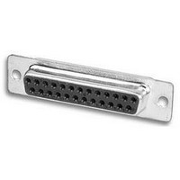
DB25-PD
Description
D SUB CONNECTOR, STANDARD, 25POS, PLUG
Manufacturer
MULTICOMP
Series
DPDr
Datasheet
1.DB25-PD.pdf
(40 pages)
Specifications of DB25-PD
Connector Shell Size
DB
Connector Body Material
Metal
Contact Material
Phosphor Bronze
No. Of Contacts
25
Connector Type
D Sub
For Use With
DPD Series D-Sub Connectors
Lead Free Status / RoHS Status
Lead free / RoHS Compliant


Adam Technologies, Inc.
INTRODUCTION:
Adam Tech Combination Signal/Coax D-Sub connectors are a
popular interface for many mixed signal I/O applications. Offered in
five shell sizes they are a good choice for a low cost industry standard
connection that requires utilization of standard signal and high
performance, low impedance signals either in signal-coax or signal -
power choices. Adam Tech connectors are manufactured with
precision stamped standard signal contacts and precision turned coax
contacts. These connectors are manufactured with precision stamped
contacts offering a choice of contact plating and a wide selection of
mating and mounting options.
Electrical:
Operating voltage: 250V AC / DC max.
Signal Current rating: 5 Amps max.
High Power contact current rating: 20 or 40 Amps.
Coaxial Impedance: 50Ω (75Ω optional)
Contact resistance: 20 mΩ max. initial
Insulation resistance: 5000 MΩ min.
Dielectric withstanding voltage: 1000V AC for 1 minute
APPROVALS AND CERTIFICATIONS:
UL Recognized File No. E224053
CSA Certified File No. LR1578596
5W5
909 Rahway Avenue
9W4
1W1
21W4
25W3
36W4
13W6
17W5
SHELL CONFIGURATIONS
2W2
7W2
•
11W1
Union, New Jersey 07083
3W3
24W7
43W2
27W2
21W1
17W2
COMBINATION SIGNAL WITH COAX OR POWER
8W8
13W3
5W1
U L
®
•
T: 908-687-5000
RoHS
COMPLIANT
RoHS
COMPLIANT
2002 / 95 / EC
2002 / 95 / EC
®
Pb
®
TYPE
SIGNAL-COAX
SIGNAL-POWER
D E
PTP= Plug, Straight PCB,
STP= Socket, Straight PCB,
PLP= Plug, Right Angle PCB,
SLP= Socket, Right Angle
PDP= Plug, Solder Cup
SDP= Socket, Solder Cup
V
PD = Plug, Solder Cup
SD = Socket, Solder Cup
PT = Plug, Straight PCB
ST = Socket, Straight PCB
PL = Plug, Right Angle PCB
SL = Socket, Right Angle PCB
•
SHELL
CONFIGURATIONS
D1W1, D2W2, D3W3,
D5W1, D5W5, D7W2,
D8W8, D9W4N,
D11W1, D13W3,
D13W6, D17W2,
D17W5, D21W1,
D21W4, D24W7,
D25W3, D27W2,
D36W4, D43W2
F: 908-687-5710
Power Contacts
Power Contacts
Power Contacts
PCB, Power Contacts
Power Contacts
Power Contacts
D13W3
ORDERING INFORMATION
D-SUBMINIATURE
•
WWW.ADAM-TECH.COM
SLP
RATING
SIGNAL- COAX
1 = 50 Ohm
2 = 75 Ohm
SIGNAL -POWER
3 = 10 Amps
4 = 20 Amps
5 = 30 Amps
6 = 40 Amps
7 = 50 Amps
MOUNTING RIGHT ANGLE
3A = Long Bracket with
MOUNTING STRAIGHT
BL = Riveted Board Locks
2A = Short Bracket with
JS = Riveted #4-40 Jack
SL = Riveted #4-40 clinch
2 = Short Bracket with
3 = Long Bracket with
1 = 120" non-threaded
1
#4-40 flush threaded
inserts in mounting
holes
#4-40 flush threaded
inserts in mounting
holes
installed
#4-40 flush threaded
inserts in mounting
holes
#4-40 flush threaded
inserts in mounting
holes
installed
Screws on top of flange
nuts on bottom of flange
mounting holes,
no bracket
Jack Screws
Jack Screws
DSC SERIES
2
81
Related parts for DB25-PD
Image
Part Number
Description
Manufacturer
Datasheet
Request
R

Part Number:
Description:
D SUB SHELL, PLUG, SIZE DB, STEEL
Manufacturer:
Cinch Connectors

Part Number:
Description:
D SUB SHELL, PLUG, SIZE DB, STEEL
Manufacturer:
Amphenol Commercial Products
Datasheet:
Part Number:
Description:
D SUB SHELL, RECEPTACLE, SIZE DB, STEEL
Manufacturer:
Amphenol Commercial Products
Datasheet:

Part Number:
Description:
IC, LINEAR VOLTAGE REGULATOR, 15V, TO-92
Manufacturer:
MULTICOMP
Datasheet:

Part Number:
Description:
Switch Cap
Manufacturer:
MULTICOMP
Datasheet:


Part Number:
Description:
COAXIAL CABLE, 100MM, BLACK
Manufacturer:
MULTICOMP
Datasheet:

Part Number:
Description:
FUSE, PTC RESET, 16V, 3A, RADIAL
Manufacturer:
MULTICOMP
Datasheet:
Part Number:
Description:
FUSE, PTC RESET, 16V, 4A, RADIAL
Manufacturer:
MULTICOMP
Datasheet:
Part Number:
Description:
FUSE, PTC RESET, 16V, 5A, RADIAL
Manufacturer:
MULTICOMP
Datasheet:

Part Number:
Description:
FUSE, PTC RESET, 30V, 1.85A, RADIAL
Manufacturer:
MULTICOMP
Datasheet:

Part Number:
Description:
FUSE, PTC RESET, 30V, 4A, RADIAL
Manufacturer:
MULTICOMP
Datasheet:

Part Number:
Description:
FUSE, PTC RESET, 60V, 170mA, RADIAL
Manufacturer:
MULTICOMP
Datasheet:

Part Number:
Description:
FUSE, PTC RESET, 90V, 200mA, RADIAL
Manufacturer:
MULTICOMP
Datasheet:
Part Number:
Description:
FUSE, PTC RESET, 90V, 250mA, RADIAL
Manufacturer:
MULTICOMP
Datasheet:
Part Number:
Description:
FUSE, PTC RESET, 90V, 400mA, RADIAL
Manufacturer:
MULTICOMP
Datasheet:
Part Number:
Description:
FUSE, PTC RESET, 90V, 900mA, RADIAL
Manufacturer:
MULTICOMP
Datasheet: