3-140 Cinch Connectors, 3-140 Datasheet - Page 80
3-140
Manufacturer Part Number
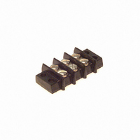
3-140
Description
CONN BARRIER BLOCK .375" 3 POS
Manufacturer
Cinch Connectors
Series
140r
Type
Wire to Boardr
Specifications of 3-140
Terminal Block Type
Barrier Block
Number Of Circuits
3
Number Of Positions
6
Pitch
0.375" (9.53mm)
Number Of Rows
2
Current
15A
Voltage
250V
Wire Gauge
16 AWG
Mounting Type
Chassis Mount or Panel Mount
Top Termination
Screws
Bottom Termination
Closed
Barrier Type
2 Wall (Dual)
Features
Flange
Color
Black
Operating Temperature
-55°F ~ 300°F
Material - Insulation
Phenol Formaldehyde (Phenolic)
Material Flammability Rating
UL94 V-1
Product
Barrier Terminal Blocks
Number Of Positions / Contacts
3
Current Rating
15 A
Voltage Rating
250 V
Wire Gauge Max (awg)
16
Current, Rating
15 A (Max.)
Length
1.782 in.
Material, Block
Phenolic
Material, Screw
Steel
Mounting Style
Bottom Mount
Plating, Screw
Nickel over Copper Flash
Screw Size
5-40 x 3⁄16
Temperature Range
-55 to +300 °F
Lead Free Status / RoHS Status
Lead free / RoHS Compliant
Lead Free Status / RoHS Status
Lead free / RoHS Compliant, Lead free / RoHS Compliant
Other names
3-140-P
3140-P
CBB103
3140-P
CBB103


3
C48 Series
Cinch Numbers
Military Standard Part Numbers
You can use MS* as well as C48
Series part numbers when ordering
C48 Series connectors.
*MS part numbers are supplied less
cable support. If cable support is
desired, it must be ordered separately.
Part numbers for the contacts and assembly tools are listed on page 3-12.
Call Toll Free: 1 (800) 323-9612
Series Designation
C48 --
Coupling Style
0 -- Threaded
1 -- Bayonet
Shell Style
0 -- Square Flange Receptacle
3 -- Single-Hole Mounting Receptacle
6 -- Straight Plug
Environmental Class
R -- Meets MIL-C-26500 (USAF)
Military Designation
MS24264 -- Square-Flange Receptacle
MS24265 -- Single-Hole Mounting Receptacle
MS24266 -- Straight Plug
Environmental Class
R -- Meets MIL-C-26500 (USAF)
Shell Size
8, 10, 12, 14, 16, 18, 20, 22, or 24
MS24266 R 22 T 55 P 6
C48-0 6 R 22-55 P 6-102
How to Order
3-3
Shell Size
8, 10, 12, 14, 16, 18, 20, 22, 24
Insert Arrangements
(See page 3-4)
Insert Arrangements
(See page 3-4)
Alternate Shell Positions
N, 6, 7, 8, 9, Y per table on page 3-4
Contact Style
P -- Pin
S -- Socket
Coupling Style
T -- Threaded
B -- Bayonet
Order Code (Deviations)
100 - Connector With Contacts & Cable Support
102 - Connector Less Cable Support With Contacts
105 - Connector Less Contacts With Cable Support
106 - Connector Less Contacts & Less Cable Support
See order codes for Boeing on page 3-14
Alternate Shell Positions
6, 7, 8, 9, 10 per table on page 3-4
(Omit for normal position)
Contact Style
P -- Pin
S -- Socket
Related parts for 3-140
Image
Part Number
Description
Manufacturer
Datasheet
Request
R

Part Number:
Description:
CONN BARRIER BLOCK .438" 3 POS
Manufacturer:
Cinch Connectors
Datasheet:

Part Number:
Description:
Terminal Block,6 Contacts,0.44 Pitch
Manufacturer:
Cinch Connectors

Part Number:
Description:
CONN BARRIER BLOCK .563" 3 POS
Manufacturer:
Cinch Connectors
Datasheet:

Part Number:
Description:
CONN BARRIER BLOCK .375" 3 POS
Manufacturer:
Cinch Connectors
Datasheet: