5-140-Y Cinch Connectors, 5-140-Y Datasheet
5-140-Y
Specifications of 5-140-Y


Related parts for 5-140-Y


5-140-Y Summary of contents
Page 1
COMMERCIAL Barrier Blocks Circular Mini DIN BNC Jones Plugs Edge Connectors ...
Page 2
... D-Microminiature] Cinch Commercial Products, consisting of Jones Plugs and Sockets, Barrier Blocks, Edge Cards, Two-Piece Commercial Dins, Mini Din Plugs, and their newest addition the 75Ω Press-Fit BNC Receptacle, provide a wide variety of connectors for the purchaser and designer to chose from. The Jones Plugs and Sockets have been utilized for decades and provide a quick, reliable, and economical means of solving your higher current-carrying capacity needs. Available in two series (300 and 2,400), these connectors can be found in data processing controls ...
Page 3
... Interposing barriers between terminals yield higher electrical ratings and provide additional protection against frayed wire shorting. ■ A wide variety of barrier blocks makes it possible to select the combination of mechanical and electrical characteristics that best meet the exact requirements of your application. ■ A wide selection of optional terminals and fanning strips permits the equipment designer to choose the method of termination most suitable for his environmental specifications and manufacturing requirements ...
Page 4
... Rating Size Terminal 250 Volts 15 Amps #16 3750 250 Volts 20 Amps #14 5000 250 Volts 30 Amps #10 7500 250 Volts 40 Amps #10 10,000 250 Volts 50 Amps #8 12,500 250 Volts 70 Amps #6 54,000 250 Volts 15 Amps #14 3750 600 Volts 15 Amps #16 3750 600 Volts 20 Amps #14 5000 600 Volts ...
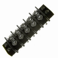
Page 5
... Barrier Blocks Series 140 Electrical Characteristics Voltage Rating: 250 VAC RMS maximum Current Rating: 15 Amps maximum Maximum Watts Per Terminal: 3750 Mechanical Characteristics Maximum Wire Size: #16 AWG Recommended Tightening Torque: 9 lb.-in. Dimensions Ordering Information No. of Terminals Call Toll Free: 1 (800) 323-9612 .375 Density, 5-40 x 3/16" ...
Page 6
... Catalog No. Y-140 3/4W-140 W-140 2-5 “W” Terminals Catalog No. 1-140-W 2-140-W 3-140-W 4-140-W 5-140-W 6-140-W 7-140-W 8-140-W 9-140-W 10-140-W 11-140-W ...
Page 7
... MS-9-140-Y MS-10-140 MS-10-140-Y MS-11-140 MS-11-140-Y MS-12-140 MS-12-140-Y MS-13-140 MS-13-140-Y MS-14-140 MS-14-140-Y MS-15-140 MS-15-140-Y MS-16-140 MS-16-140-Y MS-17-140 MS-17-140-Y MS-18-140 MS-18-140-Y MS-19-140 MS-19-140-Y MS-20-140 MS-20-140-Y MS-21-140 MS-21-140-Y MS-22-140 MS-22-140-Y MS-23-140 MS-23-140-Y MS-24-140 MS-24-140-Y MS-25-140 MS-25-140-Y 2-6 “Y” Terminal Marketed exclusively through distribution. ...
Page 8
... Barrier Blocks Series 141 Electrical Characteristics Voltage Rating: 250 VAC RMS maximum Current Rating: 20 Amps maximum Maximum Watts Per Terminal: 5000 Mechanical Characteristics Maximum Wire Size: #14 AWG Recommended Tightening Torque: 12 lb.-in. Dimensions Ordering Information No. of Terminals Call Toll Free: 1 (800) 323-9612 .438 Density, 6-32 x 1/4" ...
Page 9
... Density, 6-32 x 1/4" BH Screw, Open Bottom, Double Row “3/4W” Terminals “W” Terminals Catalog No. Catalog No. 1-141-3/4W 1-141-W 2-141-3/4W 2-141-W 3-141-3/4W 3-141-W 4-141-3/4W 4-141-W 5-141-3/4W 5-141-W 6-141-3/4W 6-141-W 7-141-3/4W 7-141-W 8-141-3/4W 8-141-W 9-141-3/4W 9-141-W 10-141-3/4W 10-141-W 11-141-3/4W 11-141-W 12-141-3/4W 12-141-W 13-141-3/4W ...
Page 10
... MS-3-141 MS-3-141-Y MS-4-141 MS-4-141-Y MS-5-141 MS-5-141-Y MS-6-141 MS-6-141-Y MS-7-141 MS-7-141-Y MS-8-141 MS-8-141-Y MS-9-141 MS-9-141-Y MS-10-141 MS-10-141-Y MS-11-141 MS-11-141-Y MS-12-141 MS-12-141-Y MS-13-141 MS-13-141-Y MS-14-141 MS-14-141-Y MS-15-141 MS-15-141-Y MS-16-141 MS-16-141-Y MS-17-141 MS-17-141-Y MS-18-141 MS-18-141-Y MS-19-141 MS-19-141-Y MS-20-141 MS-20-141-Y 2-10 Marketed exclusively through distribution. ...
Page 11
... Barrier Blocks Series 142 Electrical Characteristics Voltage Rating: 250 VAC RMS maximum Current Rating: 30 Amps maximum Maximum Watts Per Terminal: 7500 Mechanical Characteristics Maximum Wire Size: #10 AWG Recommended Tightening Torque: 16 lb.-in. Dimensions Ordering Information No. of Terminals Call Toll Free: 1 (800) 323-9612 .563 Density, 8-32 x 5/16" ...
Page 12
... Solder Terminals can be ordered separately. Terminal Type “Y” “3/4W” “W” .563 Density, 8-32 x 5/16" BH Screw, Open Bottom, Double Row “3/4W” Terminals Catalog No. 1-142-Y 1-142-3/4W 2-142-Y 2-142-3/4W 3-142-Y 3-142-3/4W 4-142-Y 4-142-3/4W 5-142-Y 5-142-3/4W ...
Page 13
... Use Standard Marker Strips for “3/4W” and “W” Solder Terminals. Accessories • Jumpers • Fanning Strips Call Toll Free: 1 (800) 323-9612 .563 Density, 8-32 x 5/16" BH Screw, Open Bottom, Double Row Catalog No. Catalog No. MS-1-142 MS-1-142-Y MS-2-142 MS-2-142-Y MS-3-142 MS-3-142-Y MS-4-142 ...
Page 14
... Density, 10-32 x 5/16" Barrier Blocks BH Screw, Open Bottom, Series 150 Double Row Electrical Characteristics Voltage Rating: 250 VAC RMS maximum Current Rating: 40 Amps maximum Maximum Watts Per Terminal: 10,000 Mechanical Characteristics Maximum Wire Size: #10 AWG Recommended Tightening Torque: 20 lb.-in. ...
Page 15
... Marker Strips Dimensions Standard .688 TYP (17.46) Ordering Information No. of Terminals Accessories None Available for 150 Series. .688 Density, 10-32 x 5/16" BH Screw, Open Bottom, Double Row Catalog No. Catalog No. MS-1-150 MS-1-150-Y MS-2-150 MS-2-150-Y MS-3-150 MS-3-150-Y MS-4-150 MS-4-150-Y MS-5-150 MS-5-150-Y MS-6-150 MS-6-150-Y MS-7-150 MS-7-150-Y ...
Page 16
... Solder Terminals can be ordered separately. Terminal Type “W” Call Toll Free: 1 (800) 323-9612 .875 Density, 12-32 x 3/8" BH Screw, Open Bottom, Double Row “M” Dim. (in) 1.750 2.625 3.500 4.375 5.250 6.125 7.000 7.875 Catalog No. ...
Page 17
... Ordering Information No. of Terminals Catalog No. 1 1-152 2 2-152 3 3-152 4 4-152 5 5-152 6 6-152 Accessories None Available for 152 Series. 1.25 Density, 1/4-28 x 1/2" BH Screw, Open Bottom, Double Row “M” “L” Dim. (in) Dim. (in) 2.250 2.876 3.375 4.001 4.500 5.126 5.625 6.251 6.750 7 ...
Page 18
... Barrier Blocks Series 164 Electrical Characteristics Voltage Rating: 250 Volts maximum Current Rating: 15 Amps maximum Maximum Watts Per Terminal: 3750 Mechanical Characteristics Maximum Wire Size: #14 Recommended Tightening Torque: 12 lb.-in. Dimensions Ordering Information No. of Terminals Call Toll Free: 1 (800) 323-9612 .375 Density, 6-32 x 5/16" ...
Page 19
... Terminals Ordering Information No. of Terminals .375 Density, 6-32 x 1/4" BH Screw, Open Bottom, Double Row “3/4W” Terminals Catalog No. Catalog No. 1-164-Y 1-164-3/4W 2-164-Y 2-164-3/4W 3-164-Y 3-164-3/4W 4-164-Y 4-164-3/4W 5-164-Y 5-164-3/4W 6-164-Y 6-164-3/4W 7-164-Y 7-164-3/4W 8-164-Y 8-164-3/4W 9-164-Y 9-164-3/4W 10-164-Y 10-164-3/4W ...
Page 20
... MS-4-140 MS-4-140-Y MS-5-140 MS-5-140-Y MS-6-140 MS-6-140-Y MS-7-140 MS-7-140-Y MS-8-140 MS-8-140-Y MS-9-140 MS-9-140-Y MS-10-140 MS-10-140-Y MS-11-140 MS-11-140-Y MS-12-140 MS-12-140-Y MS-13-140 MS-13-140-Y MS-14-140 MS-14-140-Y MS-15-140 MS-15-140-Y MS-16-140 MS-16-140-Y MS-17-140 MS-17-140-Y MS-18-140 MS-18-140-Y MS-19-140 MS-19-140-Y MS-20-140 MS-20-140-Y MS-21-140 MS-21-140-Y 2-22 Marketed exclusively through distribution. ...
Page 21
... Call Toll Free: 1 (800) 323-9612 .375 Density, 5-40 x 1/4" BH Screw, Closed Bottom, Double Row “M” Catalog No. Dim. (in) 2-540 1.125 3-540 1.500 4-540 1.875 5-540 2.250 6-540 2.625 7-540 3.000 8-540 3.375 9-540 3.750 10-540 4.125 11-540 4.500 12-540 4.875 13-540 5 ...
Page 22
... Barrier Blocks Series 541 Electrical Characteristics Voltage Rating: 600 Volts maximum Current Rating: 20 Amps Maximum Watts Per Terminal: 5000 Mechanical Characteristics Maximum Wire Size: #14 Recommended Tightening Torque: 12 lb.-in. Dimensions Ordering Information No. of Terminals Catalog No. 2 2-541 3 3-541 4 4-541 5 5-541 6 6-541 7 7-541 ...
Page 23
... Barrier Blocks Series 542 Electrical Characteristics Voltage Rating: 600 Volts maximum Current Rating: 30 Amps Maximum Watts Per Terminal: 7500 Mechanical Characteristics Maximum Wire Size: #10 Recommended Tightening Torque: 16 lb.-in. Dimensions Ordering Information No. of Terminals Catalog No 10-542 11 11-542 12 12-542 13 13-542 14 14-542 15 15-542 16 16-542 ...
Page 24
... Barrier Blocks Series 176 Electrical Characteristics Voltage Rating: 250 Volts maximum Current Rating: 15 Amps maximum Maximum Watts Per Terminal: 3750 Mechanical Characteristics Maximum Wire Size: 16 AWG Recommended Tightening Torque: 16 lb.-in. Dimensions L M Ordering Information With Mounting Ears No. of Catalog No. Terminals .125 Tail Lgth ...
Page 25
... .062 1.57 .146 3.71 .094 .078 1.98 .152 3.86 .125 .094 2.39 .177 4.50 .125 .593 15.06 .093 2.36 .091 .781 19.83 .125 3.18 .103 .906 23.01 .125 3.18 .126 .063 1.60 .146 3.71 .094 .078 1.98 .152 3.86 .125 .094 2 ...
Page 26
... Screws are brass binder head type with nickel plating. Terminals are brass with tin plating. Includes two mating clamps and one screw. Ordering Information Barrier Block Series Catalog No. 141, 541 QC-1 6-32x5/16" 142, 542 QC-2 8-32x3/8" Jumpers For connecting between adjacent terminals or alternate terminals ...
Page 27
... Barrier Block Accessories ■ Minimize wiring errors. ■ Available in straight and right-angle styles. ■ Available with cable clamp hole on right or left side, designated by “L” or “R” at end of catalog number. ■ Cable clamp hole for securing cable/wires with lacing twine or ty-wrap. ...
Page 28
... Marketed exclusively through distribution. 2-31 Catalog No. 2-160B-L 3-160B-L ...
Page 29
... Catalog No. 2-160A-L 3-160A-L 4-160A-L 5-160A-L 6-160A-L 7-160A-L 8-160A-L 9-160A-L 10-160A-L 11-160A-L 12-160A-L 13-160A-L 14-160A-L 15-160A-L 16-160A-L 17-160A-L 18-160A-L 19-160A-L 20-160A-L 21-160A-L Marketed exclusively through distribution. ...
Page 30
... Fanning Strips Dimensions Catalog No. 5-161-R Dimensions Catalog No. 5-161A-R Call Toll Free: 1 (800) 323-9612 2-33 2 Marketed exclusively through distribution. ...
Page 31
... Catalog No. 2-162A-L 3-162A-L 4-162A-L 5-162A-L 6-162A-L 7-162A-L 8-162A-L 9-162A-L 10-162A-L 11-162A-L 12-162A-L 13-162A-L 14-162A-L 15-162A-L 16-162A-L 17-162A-L 2-34 Dimensions Catalog No. 5-162-R Dimensions Catalog No. 5-162A-R Marketed exclusively through distribution. ...
Page 32
... Accessories Materials Insulation Material rated XPC, chocolate Contact Material: Steel Contact Plating: Cadmium Mechanical Characteristics Mounting Hole: .140" (3.56mm) diameter Strip Dimension: .0625" (1.59mm) thick x .375" (9.53mm) wide Lug Density: .375" (9.53mm) Ordering Information Mounting Lug Type Used In Position Catalog No. Centers ...
Page 33
... Jones Plugs/Sockets Series 300 ■ Solder lug terminals with .093" x .062" (2.36mm x 1.57mm) wiring holes. ■ Two-contact "Jones" connector is round, all others are rectangular. ■ For use in cable-to-panel and cable-to-cable applications. ■ Designed for light and medium duty. ■ Plug prongs are .156" (3.96mm) wide and .047" (1.19mm) thick. ...
Page 34
Jones Plugs/Sockets Series 300 Polarizing Patterns - 300 Series Multiple Density Solder Eyelet Marketed exclusively through distribution. Call Toll Free: 1 (800) 323-9612 2-37 ...
Page 35
... NOTE: For 300 Series 2 through 33 contact angle bracket connectors. All mounting holes are .156" (3.96mm) dia. Maximum chassis thickness is .063" (1.59mm) for bottom mounting. Mounting holes are located on center line unless otherwise shown. Call Toll Free: 1 (800) 323-9612 ...
Page 36
... NOTE: 15-position plug and socket require only two mounting brackets, mounted on center of connector. [.050” (1.27mm) Density Multiple Density Solder Cup/Wire Solder Eyelet With Angle D-Microminiature] Bracket/Less Angle Bracket No. of Catalog No. Contacts 2 P-302-LAB ...
Page 37
... Plugs/Sockets High Reliability All-Plastic Series 300 300 Series with Flush Plate (FP) No. of Catalog No. Contacts Plug 2 P-302-FP 3 P-303-FP 4 P-304- P-306-FP 8 N/A 10 P-310-FP 12 P-312-FP NOTE: Not available in contact sizes 15-33. Dimensions - Plug or Socket No Contacts 2.063 52.40 3 2.063 52.40 4 2.063 52.40 6 2.063 52. 2.563 65. ...
Page 38
... End Brackets Socket S-315-EB S-318-EB S-321-EB S-324-EB S-328-EB S-330-EB S-333- length of plug contacts. This dimension does not apply to sockets length of plug or socket tails. M ± .031 (.79mm) ± .063 (1.59mm) 2.000 50.80 1.625 2.313 58.75 1.938 2.625 66.68 2.250 2.938 74.63 2.563 3 ...
Page 39
... High Reliability Series 300 All-Plastic 300 Series with Recessed Plate (RP) No. of Catalog No. Contacts Plug 2 P-302-RP 3 P-303-RP 4 P-304-RP 6 P-306- N/A 10 P-310-RP 12 P-312-RP NOTE: Not available in contact sizes 15-33 length of plug or socket tails. Dimensions No Contacts 2.063 52.40 3 2.063 52.40 4 2.063 52.40 6 2.063 52. ...
Page 40
... X = length of plug contacts. This dimension does not apply to sockets length of plug or socket tails. L ± .063 (1.59mm) Polarizing in mm Pin 2.547 64.69 NO 2.859 72.62 NO 3.172 80.57 NO 3.484 88.49 14 3.797 96 ...
Page 41
... Call Toll Free: 1 (800) 323-9612 [.050” (1.27mm) Density Multiple Density Solder Cup/Wire Solder Eyelet D-Microminiature] Deep Bracket Catalog No. Socket S-302-DB S-303-DB S-304-DB S-306-DB N/A N/A N/A ...
Page 42
... Jones [.050” (1.27mm) Density Plugs/Sockets Solder Cup/Wire Series 300 D-Microminiature] 300 Series with Hood and 90° Cable Clamp (CCE) No. of Catalog No. Catalog No. Contacts Plug 2 P-302-CCE S-302-CCE 3 P-303-CCE S-303-CCE 4 P-304-CCE S-304-CCE 6 P-306-CCE S-306-CCE 8 N/A 10 P-310-CCE 12 P-312-CCE 15 P-315-CCE S-315-CCE 18 P-318-CCE S-318-CCE 21 P-321-CCE ...
Page 43
... No. of Contacts Call Toll Free: 1 (800) 323-9612 [.050” (1.27mm) Density Multiple Density Solder Cup/Wire Solder Eyelet With Hood & 180° Clamp D-Microminiature] Catalog No. Socket S-302-CCT S-303-CCT S-304-CCT S-306-CCT N/A N/A N/A S-315-CCT S-318-CCT S-321-CCT ...
Page 44
... Jones [.050” (1.27mm) Density Plugs/Sockets Solder Cup/Wire Series 300 D-Microminiature] 300 Series Plug with Hood and Lock (CCT-L) and Socket with Hood and Keeper (CCT-K) No. of Catalog No. Catalog No. Contacts Plug w/ Lock Socket w/ Keeper 2 P-302-CCT-L S-302-CCT-K 3 P-303-CCT-L S-303-CCT-K 4 P-304-CCT-L S-304-CCT-K 6 P-306-CCT-L ...
Page 45
... Call Toll Free: 1 (800) 323-9612 [.050” (1.27mm) Density Multiple Density Solder Cup/Wire Solder Eyelet D-Microminiature] PLUGS ...
Page 46
... Plugs and sockets have recessed pockets with barriers around the contacts. ■ A shoulder extends around the face (mating) side of both plug and socket presenting a finished appearance when mounted in bracket or cap. ■ Intermates with existing 400 Series Products on the market. ...
Page 47
... Multiple Density Solder Eyelet Less Angle Bracket Socket Socket 14.29 .656 16.67 25.40 1.094 27.78 36.51 1.531 38.89 47.63 1.969 50.01 58.74 2.406 61.12 69.85 1.844 46.83 2-51 Marketed exclusively through distribution. Call Toll Free: 1 (800) 323-9612 ...
Page 48
... Panel Cutout dimensions are on page 2-61. Call Toll Free: 1 (800) 323-9612 [.050” (1.27mm) Density Multiple Density Solder Cup/Wire Solder Eyelet D-Microminiature] With Angle Bracket Catalog No. Socket S-2402-AB S-2404-AB S-2406-AB S-2408-AB S-2410-AB S-2412-AB Socket ...
Page 49
... Panel Cutout dimensions are on page 2-61. [.050” (1.27mm) Density Multiple Density Solder Cup/Wire Solder Eyelet D-Microminiature] Shallow Bracket Catalog No. Socket S-2402-SB S-2404-SB S-2406-SB S-2408-SB S-2410-SB S-2412- 1.062 26.99 1 ...
Page 50
... Panel Cutout dimensions are on page 2-61. Call Toll Free: 1 (800) 323-9612 [.050” (1.27mm) Density Multiple Density Solder Cup/Wire Solder Eyelet D-Microminiature] Deep Bracket Catalog No. Socket S-2402-DB S-2404-DB S-2406-DB S-2408-DB S-2410-DB S-2412-DB Socket ...
Page 51
... Jones [.050” (1.27mm) Density Plugs/Sockets Solder Cup/Wire Series 2400 D-Microminiature] 2400 Series with Hood and 90° Clamp No. of Catalog No. Catalog No. Contacts Plug 2 N/A S-2402-CCE 4 P-2404-CCE S-2404-CCE 6 P-2406-CCE S-2406-CCE 8 P-2408-CCE S-2408-CCE 10 P-2410-CCE S-2410-CCE 12 P-2412-CCE S-2412-CCE Dimensions - Plug or Socket No Contacts .625 15. ...
Page 52
... With Hood & 180° Clamp Catalog No. Socket S-2402-CCT S-2404-CCT S-2406-CCT S-2408-CCT S-2410-CCT S-2412-CCT L Cable Opening .625 15.88 .313 1.062 26.99 .438 1.500 38.10 .438 1.937 49.21 .563 2.375 60.33 .563 2.813 71.45 .625 2-56 mm 7.94 11.11 11.11 14.29 14.29 15.88 Marketed exclusively through distribution. ...
Page 53
... P-2404-DB S-2404-DB 1.750 44.46 P-2406-DB S-2406-DB 2.188 55.56 P-2408-DB S-2408-DB 2.624 66.68 P-2410-DB P-2410-DB 3.062 77.80 P-2412-DB S-2412-DB 3.500 88.90 [.050” (1.27mm) Density Solder Cup/Wire Panel Cutout Dimensions D-Microminiature 1.008 25.60 1.015 25.78 1.445 36.70 1.015 25.78 1.886 47 ...
Page 54
... Circular Mini DIN Plugs ■ Contact positions and 8. ■ Pre-assembled with standard shielded cable lengths; consult factory for other lengths. ■ Molded-in strain relief. ■ Cable and overmold available in standard colors: black or beige. ■ Contacts available with gold over nickel. ■ Shielding system designed to meet FCC requirements for EMI/RFI suppression. ...
Page 55
... MDC-4P13 MDC-4P53 3 MDC-4P15 MDC-4P55 1 MDC-5P05 MDC-5P08 1 MDC-6P05 MDC-6P08 2 MDC-6P13 MDC-6P53 3 MDC-6P15 MDC-6P55 1 MDC-7P05 MDC-7P08 2 MDC-7P13 MDC-7P53 3 MDC-7P15 MDC-7P55 1 MDC-8P05 MDC-8P08 2 MDC-8P13 MDC-8P53 3 MDC-8P15 MDC-8P55 Black Color Beige Color Cable & Cable & Overmold Overmold Catalog No. Catalog No. 1 MDC-3P06 MDC-3P09 1 MDC-4P06 MDC-4P09 1 ...
Page 56
... Circular Mini DIN Plugs ■ Individual components available for cable assembly with overmolding. ■ Plug insulator available with contact positions and 8. ■ Seamless shield case is crimped to cable shield; designed to meet FCC requirements for EMI/RFI suppression. ■ One-piece shield case - no extra ferrules or shields required with Cinch Shield Crimp Tools. ■ ...
Page 57
... Pneumatic Crimp Tool Overview of Assembly Steps • Prepare multi-conductor cable. • Crimp contacts onto individual conductors using tool MDT-P25 or tool MDT-P35. • Insert contact with conductor into insulator using tool MDT-P41 or have insertion tool MDT-P28 with insulator locating vice MDT-P29. • Insert insulator into the shield case using tool MDT-P34 or MDT-P30. ...
Page 58
... Dip solder tails on .200" (5.08mm) row centers double readout. ■ Bifurcated semi-bellows contacts for added contact reliability. ■ Ideal for applications involving vibration or board irregularities. ■ Contact positions: 12, 15, 18, 20, 22, 25, 28, 30, 31, 36, 37, 40, 43, 44, 49, 50, 52, 60, 70, AT, and XT. ■ Accepts .062" (1.59mm) thick PC boards. ...
Page 59
... IBM 50-31SN-XT 36/72 50-36SN-12 37/74 50-37SN-12 40/80 50-40SN-12 43/86 50-43SN-12 44/88 50-44SN-12 49/98 50-49SN-12 50/100 50-50SN-12 52/104 50-52SN-12 60/120 50-60SN-12 70/140 50-70SN-12 .100" (2.54mm) Density Dip Solder 27.94 1.300 33.02 1.460 37.08 35.56 1.600 40.64 1.760 44.70 43.18 1.900 48.26 2 ...
Page 60
... CARDCON ™ Edge Connector Commercial ■ Dip solder tails single readout and double readout on .140" (3.56mm) row centers or .200" (5.08mm) row centers. ■ Solder eyelet, single readout and double readout on .200" (5.08mm) row centers. ■ Available with unique tails for PC board retention; holds the connector firmly on the board during wave soldering operations. ■ ...
Page 61
... Less Mounting Ears .128 Mounting Hole Pos./Cont. Catalog No. Catalog No. Dip solder tails, double readout, .140" (3.55mm) row spacing, .125" (3.18mm) long 6/12 50-12SN-4 50-12SN-2 10/20 50-20SN-4 50-20SN-2 12/24 50-24SN-4 50-24SN-2 15/30 ...
Page 62
... Edge Connector High Reliability ■ Dip solder tails, single readout, .156" (3.96mm) long or .234" (5.94mm) long. ■ Dip solder tails, double readout, .156" (3.96mm) or .234" (5.94mm) long on .200" (5.08mm) row spacing, or .125" (3.18mm) long on .140" (3.56mm) row spacing. ■ Solder eyelet, single readout and double readout on .200" (5.08mm) row spacing. ...
Page 63
... Edge Connector .156" (3.96mm) Density Dip High Reliability Solder/Solder Eyelet Single Readout Double Readout With Plain Mounting Holes Dimensions No Pos./Cont 1.100 27.94 10 1.724 43.79 12 2.036 51.71 15 2.504 63.60 18 2.972 75.49 20 3.286 83.46 22 3.596 91.34 25 4.067 103. 1.239 31.47 1.531 38.80 1 ...
Page 64
... Double Readout .128" (3.25mm) Mounting Hole Solder Eyelet Dip Solder Tails No. of .234" (5.94mm) Long Pos./Cont. .200" (5.08mm) Between .200" (5.08mm) Between .140" (3.56mm) Between .140" (3.56mm) Between Row Spacing Catalog No. Catalog No. 6/12 50-12H-30 50-12S-20 10/20 50-20H-30 50-20S-20 ...
Page 65
... Accepts .062" (1.59mm) thick double-sided PC boards. Insulation Material: Diallyl phthalate, green Contact Material: Beryllium copper Contact Plating: 30µin. select gold over 50µin. nickel in the contact areas, 10µin. gold tails Shock: Per MIL-STD-202E, Method 213, Condition C Operating Temperature: -65°C to +125°C ...
Page 66
... Ordering Information No. of Pos./Cont. 6/12 10/20 12/24 15/30 18/36 22/44 25/50 .156" (3.96mm) Density Card Extender 1.239 31.47 1.531 38.88 1.864 47.34 2.156 54.76 2.177 55.29 2.469 62.71 2.645 67 ...
Page 67
... Edge Connector Accessories Card Guides Card guide for .100" (2.54mm) and .156" (3.96mm) density edge connectors. Accepts .062" (1.59mm) thick PC boards. Card guides attach to mounting ears and guide printed circuit board into connector. Order separately. Material: Polypropylene Part No. 50-GP-1 (Green) Part No. 50-GP-1B (Black) ...
Page 68
... For Hole Diameter in mm .250 6.35 .375 9.53 .500 12.70 .625 15.88 .750 19.05 .875 22.23 1.000 25.40 1.250 31.75 1.000 25.40 2-74 Cup Diameter in mm Catalog No. .406 10.32 41A .500 12.70 41B .656 16.67 41C .797 20.24 41D .938 23.81 41E 1 ...
Page 69
... Impedance. ■ Meets Lucent Technologies (AT&T) Requirements. Body: One-piece diecast zinc per QQ-Z-363 Plating: Nickel, 150µin. min. per QQ-N-290 over copper, 200µin. min. per MIL-C-14550 Center Contact: Beryllium copper Plating: Gold, 30µin. minimum over nickel, 50µin. minimum ...
Page 70
... Press-Fit BNC Coaxial Connector Board Mount Receptacle for 75 Ω Ω Applications Production Insertion Tool Design Press-Fit BNC Connector Dimensions Ordering Information Catalog Number: BNC-1-PF Standard Package: Anti-Static Tube, 48 Connectors Per Tube Call Toll Free: 1 (800) 323-9612 2-77 ...