1723 055 2101 HARTING, 1723 055 2101 Datasheet - Page 23
1723 055 2101
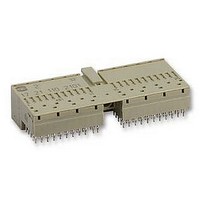
Manufacturer Part Number
1723 055 2101
Description
SOCKET, FEMALE, R/A, TYPE C, 55WAY
Manufacturer
HARTING
Series
HARBUSr
Datasheet
1.17_21_110_2101.pdf
(36 pages)
Specifications of 1723 055 2101
Connector Type
Rectangular Power
Gender
Receptacle
No. Of Contacts
55
No. Of Rows
5
Pitch Spacing
2mm
Connector Mounting
PCB
Contact Material
Copper Alloy
Svhc
No SVHC
Approval Bodies
IEC61076-4-101
Rohs Compliant
Yes
Lead Free Status / RoHS Status
Lead free / RoHS Compliant


CompactPCI
CompactPCI
hanced by the PCI Industrial Computer Manufactu-
rers Group (PICMG
the electrical and logical specifications of the PCI
standard and the mechanical specifications of the
IEEE 1101 and IEC 60297 series of standards. The
board connector has been developed from the IEC
61076-4-101 series of 2.0 mm connectors. The mo-
unting location and dimensions for the 2.0 mm
connectors are specified in IEEE 1101.11. Some
additional mechanical definitions for 2.0 mm
connectors in the Eurocard format are being speci-
fied in the VITA 30 draft. Other international stan-
dards are listed in the CompactPCI
environmental and related specifications. This gives
CompactPCI
standards and practices for mechanical robustness.
The board format is either a 3U or a 6U Eurocard as
defined in IEC 60297. There are two or five connec-
tors specified for 3U or 6U boards respectively.
Connectors are numbered from J1/P1 through
J5/P5 (bottom to top) on the board or backplane.
Slave or peripheral boards need J1/P1 as a mini-
mum, master or system boards need both J1/P1
the 2.0mm hard metric system from HARTING
®
®
®
as a standard is maintained and en-
a solid foundation of international
configuration
®
). It defines a combination of
®
standard for
and J2/P2 as a minimum. Backplanes should always
have the full complement of connectors to be com-
patible with any type of board.
Connectors, as well as contact numbers on the
connectors are both numbered from bottom to top.
This is opposite to numbering schemes in other ar-
chitectures.
The front panel of CPCI cards may be equipped with
additional keying pegs to code individual board ty-
pes. There is also an extended length pin to remove
any electro-static charge before the contacts on the
rear connnetors mate. This pin also functions as a
mechanical guide to position the board as straight
as possible for insertion. This prevents pin bending
and lowers the insertion force. There might be more
than 500 pins to be pushed into sockets, all at the
same time.
Connectors for high availability applications (hot
swap) come with 3 different lenths of pins for a sta-
ged sequence of make or break of contact.
Connector J1/P1 carries the signals for a 32 bit PCI
bus (see table of contact assignments for J1/P1).
Connector J2/P2 on a system card has the additio-
nal signals for a 64 bit PCI bus and some user-defi-
ned I/O (see table of contact assignments for
J2/P2). On slave cards all of J2/P2 might be user-
defined I/O except the top row which carries the sig-
nals for geographical addressing. J3 should be re-
served for other system bus definitions. J4/P4 and
23
Related parts for 1723 055 2101
Image
Part Number
Description
Manufacturer
Datasheet
Request
R


Part Number:
Description:
CODE COMB, DIN 41612 SHELL HOUSING D20
Manufacturer:
HARTING
Datasheet:

Part Number:
Description:
Harting Han Modular 2 Module female
Manufacturer:
HARTING
Datasheet:

Part Number:
Description:
Telecom & Ethernet Connectors Ethernet Switch HARTING mCon 3082-AD
Manufacturer:
HARTING
Datasheet:

Part Number:
Description:
Telecom & Ethernet Connectors ETHERNET SWITCH SCON 3063-AD
Manufacturer:
HARTING
Datasheet:

Part Number:
Description:
Telecom & Ethernet Connectors ETHERNET SWITCH ECON 2040-A
Manufacturer:
HARTING
Datasheet:
Part Number:
Description:
Ethernet Switch with 5 ports RJ Industrial / IP30
Manufacturer:
HARTING
Datasheet:

Part Number:
Description:
Telecom & Ethernet Connectors ETHERNET SWITCH ECON 3080-A1
Manufacturer:
HARTING
Datasheet:

Part Number:
Description:
Telecom & Ethernet Connectors ETHERNET SWITCH MCON 7050-A
Manufacturer:
HARTING
Datasheet:

Part Number:
Description:
Telecom & Ethernet Connectors ETHERNET SWITCH ECON 6050-A
Manufacturer:
HARTING
Datasheet:

Part Number:
Description:
Telecom & Ethernet Connectors ETHERNET SWITCH ECON 4080-B1
Manufacturer:
HARTING
Datasheet:
Part Number:
Description:
Manufacturer:
HARTING
Datasheet:

Part Number:
Description:
Telecom & Ethernet Connectors ETHERNET SWITCH SCON 3082-AD
Manufacturer:
HARTING
Datasheet: