2000891-1 Tyco Electronics, 2000891-1 Datasheet
2000891-1
Specifications of 2000891-1


Related parts for 2000891-1


2000891-1 Summary of contents
Page 1
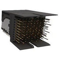
... Eye--of--Needle Compliant Pin Contact Tail End Module Double--Wide Center Module E2011 Tyco Electronics Corporation Connectivity Ltd. Company All Rights Reserved TE Connectivity, TE connectivity (logo), and TE (logo) are trademarks. *Trademark. Other logos, product and/or Company names may be trademarks of their respective owners. ...
Page 2
Left End Module Shroud Chicklet Alignment Slot (2 Places) Housing Signal Pin Contact Eye--of--Needle Ground Pin Compliant Pin Contact Tail Contact Chamfered Lead--In Left End Module Double--Wide Center Module Alignment Slot (4 Places Right- Angle Header 2--Pair, ...
Page 3
The connector system consists of a vertical receptacle (motherboard) and a right- - angle header (daughter card) consisting of a configuration of end modules, center modules, stand alone modules, double- - wide center modules, and double- - wide stand alone ...
Page 4
Connector Configuration The minimum and maximum amount of modules used in a configuration and possible connector configurations are shown in Figure 5. The configurations shown include guide hardware. 2. REFERENCE MATERIAL 2.1. Revision Summary Revisions to this application specification ...
Page 5
Guide Pin End Module Guide Left Module Module Guide Pin End Module Guide Left Module Module Rev B Connector Configurations Minimum Amount of Modules Guide Guide Vertical Receptacle Pin Pin End End Module Module Guide Guide Left Right Module Module ...
Page 6
Possible Amount of Modules Guide Vertical Receptacle Pin End Center End Module Module Module Guide Left Center Right Module Module Module Module Right--Angle Header Guide Pin Guide Module 3.3. Limitations The connector system is designed to operate in a temperature ...
Page 7
PC Board A. Material and Thickness The pc board material shall be glass epoxy (FR 10). For single plane application, the pc board thickness shall be a minimum of 1.40. For mid plane application, the ...
Page 8
Finished Hole Size and Plated Through Holes Module Outline 1.80 Ref Signal Ground BSC 3 11.78 Ref 3.58 Ref Signal Ground - - Datums and Basic Dimensions Established by Customer 4 Dimension Applies to Centerline of ...
Page 9
Placement A. Modules The module number one position must be aligned with the number one position board hole. When placing modules on the pc board, make sure that the contacts are aligned and started into the matching holes before ...
Page 10
Note: Dimensions are for Reference Only 1.9 Module Outline 0 1.9 0.9 1.9 Module 0.9 Outline 0 1.9 0 Recommended Module End- to- End Spacing (Component Side Shown) Center Modules Right--Angle Header 19 0.9 1.66 24.64 19 ...
Page 11
Note: Dimensions are for Reference Only Module 24.1 Outline 7 0 1.7 24.1 Module Outline 1.9 1.9 0 0.9 Rev B Full Shroud End Modules Right--Angle Header 1.66 0.9 0.9 24.64 7 Vertical Receptacle 1.725 1.725 1.7 Double--Wide Center Modules ...
Page 12
B. Modules and Guide Hardware The recommended minimum distance between the module and guide hardware is given in Figure 10. Recommended Module and Guide Hardware Spacing Guide Module Width Note: Modules Shown Mated B (Recommended) Min Between Module and Guide ...
Page 13
Mating Modules A. Alignment Proper alignment is essential to ensure full engagement of mating modules and that contacts are not bent or otherwise damaged during mating. Tolerance limitations for single plane application are given Figure 12. Tolerance limitations for ...
Page 14
B. Mating Force A maximum of 0.834 N [3 oz- -force] per contact is required for full mating of the modules. C. Mating Sequence and Wipe Length These connectors have three levels of sequencing during mating: first mate, last break ...
Page 15
Note: Dimensions are based on modules being fully seated on the pc board. FMLB Receptacle Header Contact Contact Beam Pin Reliable Mate and Fully Mate COMPONENT COMPONENT Plastic Housing (Alignment) Ground Contact Signal Contact Rev B Mating Sequence First Mate ...
Page 16
Mid Plane Application Alignment for mid plane applications are shown in Figure 14. Note: Guide Hardware Not Shown Note: Modules are Shown Not Mated Front View 3.8 Min Backplane Thickness Backplane (Ref) 3.8 Min Backplance Thickness Backplane (Ref) 16 ...
Page 17
Module Removal The minimum amount of extraction force per contact is 0.028 N [.10 oz- - force]. 3.12. Replacement and Repair Damaged or defective modules MUST NOT be used. The modules can be replaced a maximum of two times. ...
Page 18
VISUAL AID The illustration below shows a typical application of Fortis Zd pc board connector system. This illustration should be used by production personnel to ensure a correctly applied product. Applications which DO NOT appear correct should be inspected ...