00-8016-056-000-001 AVX Corporation, 00-8016-056-000-001 Datasheet - Page 29
00-8016-056-000-001
Manufacturer Part Number
00-8016-056-000-001
Description
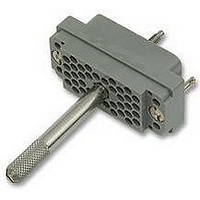
PLUG, 56WAY
Manufacturer
AVX Corporation
Series
8016r
Datasheet
1.60-8017-0313-00-042.pdf
(54 pages)
Specifications of 00-8016-056-000-001
No. Of Contacts
56
Gender
Plug
Contact Termination
Crimp
Contact Plating
Gold
Contact Material
Phosphor Bronze
Svhc
No SVHC (15-Dec-2010)
Colour
Grey
Connector Mounting
RoHS Compliant
Connector Type
Card Edge


Varicon
Series 8223 – 0.100" Dual Row Square Grid
FEATURES
TECHNICAL SPECIFICATIONS
CONTACTS
Current Rating:
5 amperes with 22 AWG wire
Contact Resistance:
6 milliohms, maximum
ORDERING CODE
28
Code
000
000
473
519
520
558
559
560
561
722
721
736
737
753
771
000
000
491
Use three digit code number when contacts are to
be factory installed. If contacts are to be supplied
loose, or contact tails to be formed, use three zeros
(000) in contact code section. Note that the wire
crimp tail contacts can only be ordered as separate
items by part numbers.
•
•
•
•
•
•
•
Wide range of contact terminations including wire
wrapping, P.C. solder tail, wire hole, wire crimp
For
Polarity and keying are built into the connector body
to prevent mismating
Perpendicular or parallel connector mounting
Proven Varicon
Protected male; recessed female contacts
Conforms to MIL-C-55302 QPL
Profile
00
1
⁄
1 6
",
Coined Tail Formed
90° after installing
(Max. 0236 Diag.)
Coined Tail Formed
90° after installing
(Max. 0236 Diag.)
P.C. Tail Coined
(Max. 0236 Diag.)
P.C. Tail Coined
(Max. 0236 Diag.)
P.C. Tail Coined
(Max. 0236 Diag.)
P.C. Tail Coined
(Max. 0236 Diag.)
P.C. Tail Coined
(Max. 0236 Diag.)
Wire Hole Tail
(.032 x .050)
P.C. Tail .020 Sq.
P.C. Tail .020 Sq.
P.C. Tail .020 Sq.
P.C. Tail .020 Sq.
P.C. Tail .020 Sq.
Crimp Contact
(Reel 3000)
22-30 AWG
Crimp Contact (Loose)
22-30 AWG
Wrappable/Removable
Contact (.025 Sq.)
3
Description
⁄
3 2
" P.C. card
®
®
contact reliability
60 8223 0223
60 8223 0213
60 8223 0243
60 8223 0253
60 8223 0233 .400
60 8223 0213 .279
60 8223 0223 .479
60 8223 0243 .309
60 8223 0253 .509
60 8223 0263 .341
60 8223 0273 .541
60 8200 1613 .162
60 8200 1623 .228
60 8200 1633 .259
60 8200 1643 .541
60 8200 1653 .103
60 8200 1663 .462
60 8216 0323
60 8216 0313
60 8216 0413 .560
Part No.
8223
Dim. Thk.
H Board
Contact Material and Plating:
Phosphor Bronze
Nickel plate, 50 to 100 micro-
inches, followed by gold plate.
10 microinches minimum
.080
.062
.093
Fig.
1
1
2
2
2
2
2
2
2
3
4
4
4
4
4
5
5
6
Number of Contacts
024, 048, 072 & 096
Insulator
Contacts)
Contacts)
(Exposed
(Exposed
024
Female
Male
Type
Variation
001
002
003
004
006
007
008
009
016
017
018
019
901
902
903
904
906
907
908
909
916
917
918
919
ELCO
ELCO
Formed Contact Terminal
Formed Contact Terminal
Formed Contact Terminal
Formed Contact Terminal
Contact Code
Wrappable Removable
Wrappable Removable
PC Straight Terminal
PC Straight Terminal
Wire Hole Terminal
Wire Hole Terminal
Crimp Contact
Crimp Contact
Contact Style
Similar to 001
Similar to 002
Similar to 004
Similar to 006
Similar to 901
Similar to 902
Similar to 904
Similar to 905
INSULATORS
Material:
Diallyl Phthalate, glass-filled,
flame resistant, per MIL-M-14-F,
Type SDGF
Insulation Resistance:
5,000 megohms, minimum
000
PC Terminal
PC Terminal
Variation Code
Cover Bracket
001
Accessories
Keying
Guide Pins Sockets (R)
X
X
X
X
X
X
X
X
X
X
X
X
X
X
Dielectric Withstanding
Voltage:
Sea Level: 1,000 Volts rms
Insertion/Withdrawal Force:
2 to 8 ounces per contact
Locking Lkg. Kyg.
X
X
X
X
X
X
X
X
Threaded
X
X
X
X
X
X
X
X
Figure Thickness
Refer
To
15
16
15
16
15
16
15
16
1
2
3
4
5
6
1
7
8
7
8
7
8
7
8
1
2
3
4
5
6
1
.080 2.03
.062 1.57
.093 2.36
.080 2.03
.062 1.57
.093 2.36
Board
Related parts for 00-8016-056-000-001
Image
Part Number
Description
Manufacturer
Datasheet
Request
R

Part Number:
Description:
PLUG, 56WAY
Manufacturer:
AVX Corporation
Datasheet:

Part Number:
Description:
SOCKET, 56WAY
Manufacturer:
AVX Corporation
Datasheet:

Part Number:
Description:
SOCKET, 56WAY
Manufacturer:
AVX Corporation
Datasheet:

Part Number:
Description:
20W FEMALE INS+ACT SCREW
Manufacturer:
AVX Corporation
Part Number:
Description:
Manufacturer:
AVX Corporation
Datasheet: