CCM03-3505LFT R122 ITT Cannon, CCM03-3505LFT R122 Datasheet
CCM03-3505LFT R122
Specifications of CCM03-3505LFT R122


Related parts for CCM03-3505LFT R122


CCM03-3505LFT R122 Summary of contents
Page 1
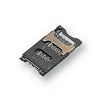
... A new range of CCM03 connectors have been developed to interface with SIM/SAM cards as defined by GSM11- 11 and ENV1375-1. The connectors are available with either hinged covers or fixed covers and have been designed to minimize the amount of space needed for PCB mounting. Features Hinged Cover • ...
Page 2
... CCM03-3011 R102 8 CCM03-3012 R102 8 CCM03-3013 R102 6 CCM03-3514 R122 6 CCM03-3504 R122 8 CCM03-3505 R122 6 Dimensional Drawings Hinged Cover CCM03 - 3001 (6 contacts) 3002 (6 contacts - PCB locating pegs) 3003 (8 contacts) 3004 (8 contacts - PCB locating pegs) 0,7 25˚0' SEE DETAIL A 29,65 5,65 0,2 13,8 3,5 2,45 R 1,9 ...
Page 3
... Insulated Card Presence Switch Dimensional Drawings Hinged Cover CCM03 - 3013 (6 contacts + Card Presence Switch) 25,5 0,2 2,1 13,15 0,7 25˚0' SEE DETAIL A 29,65 5,65 0,2 13,8 3,5 2,45 R 1,9 Slider locked Pick and place area ø 3,5 3,81 3,8 R 1,9 Note: Coplanarity of soldering surfaces: ± 0,05 mm ...
Page 4
... CCM03 MK II Hinged Cover Dimensional Drawings Hinged Cover CCM03 - 3514 (6 contacts - with switch on metal lock) 25,5 0,2 Right lock switch terminal 2,1 13,15 Left lock switch terminal 0,7 25˚0' SEE DETAIL A 29,65 5,65 0,2 13,8 3,5 2,45 R 1,9 Slider locked Bump Pick and place area ø ...
Page 5
... Pad Prohibited area 3,81 3,81 ENV1375-1 & GSM11-11 25,5 CCM03 MK II Fixed Cover Fixed cover CCM03 - 3504 (8 contacts) 12,75 2,5 DETAIL A 10,16 40˚0' SEE DETAIL A 3,81 0,8 2,65 25,5 (REF.) 0,15 min Card stop +0,05 ø 1,4 ...
Page 6
... CCM03 MK II with Auto Lock cover A new range of CCM03 connectors have been developed to interface with SIM/SAM cards as defined by GSM11- 11 and ENV1375-1. The connectors are available with a hinged metallic cover and have been designed to provide an easier open/lock function and side card entry ...
Page 7
... Plastic outline Contact foot area 1 Pad 5 16,1 Prohibited area 3,81 Contact location according to ENV1375-1 & GSM 11-11 CCM03 MK II with Auto Lock cover Hinged Cover CCM03 - 3517 (6 contacts) 0,25 LOCKED 1,3 LOCKED OPEN 1,9 Manual 1 opening Card withdrawal 2 1 from the base ...
Page 8
... Pick and place area Date Code area ø3,2 4,4 3,2 4,4 0,95 Note: Coplanarity of soldering surfaces: ± 0,05 mm PCB Layout CCM03 - 3518 (6 contacts and switch) CCM03-3529 (without switch) layout is similar except SW pads CARD WITHDRAWAL Plastic outline Contact foot area 1,5 Pad ...