S-2404H-CCT Cinch Connectors, S-2404H-CCT Datasheet - Page 69
S-2404H-CCT
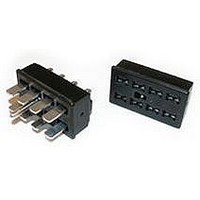
Manufacturer Part Number
S-2404H-CCT
Description
PLUG & SOCKET CONNECTOR, SOCKET, 4POS
Manufacturer
Cinch Connectors
Series
2400r
Type
Cable Socketr
Datasheet
1.140J-1.pdf
(70 pages)
Specifications of S-2404H-CCT
Contact Termination
Solder
No. Of Contacts
4
No. Of Rows
2
Connector Mounting
Cable
Gender
Receptacle
Contact Material
Phosphor Bronze
Connector Type
Plug & Socket
Agency Approvals
CSA, UL
Angle
Straight
Brand/series
2400 Series
Color
Black
Contact Plating
Cadmium
Current, Rating
15 A
Diameter
0.093 in.
Flammability Rating
UL94V-0
Length, Overall
1.062 "
Material, Contact
Phosphor Bronze
Material, Dielectric
Phenolic
Material, Hood
Metal
Material, Insulation
Phenolic Molded Monoblock
Number Of Contacts
4
Number Of Rows
2
Pin Spacing
0.5 "
Plating, Contact
Cadmium
Primary Type
Jones
Special Features
Polarized
Standards
UL Listed, CSA Certified
Temperature, Operating
0 to +105 °C
Termination
Solder
Thickness
0.055 in.
Voltage, Rating
250 V
Width
0.250 in.
Rohs Compliant
Yes
Lead Free Status / RoHS Status
Lead free / RoHS Compliant
For Use With
For use in cable-to-cable and cable-to-panel applications


Press-Fit BNC Coaxial Connector Board Mount
Receptacle for 75 Ω Ω Applications
Body: One-piece diecast zinc per QQ-Z-363
Plating: Nickel, 150µin. min. per QQ-N-290 over copper, 200µin.
Center Contact: Beryllium copper
Plating: Gold, 30µin. minimum over nickel, 50µin. minimum
Insulator: Teflon TFE per ASTM D1710
Connector Insertion Force: <500 lb.*
Connector Removal Force: >100 lb.*
Center Contact Insertion Force: < 2.0 lb.*
Center Contact Removal Force: > 2.0 oz.*
*
mounting holes. PC board thickness can range from .093" to .300" thick.
PC board hole requirements are as follows:
Call Toll Free: 1 (800) 323-9612
Requirements are for two connector insertions into the same PC board
■ Solderless, Press-Fit Installation.
■ Strong, One-Piece Cast Body.
■ Standard BNC Interface.
■ 75Ω Ω Impedance.
■ Meets Lucent Technologies (AT&T) Requirements.
Ground Legs:
Center Contact: .040" Nom.
Insulation Resistance:
Frequency Range:
min. per MIL-C-14550
Working Voltage:
Insertion Loss:
RF Leakage:
Impedance:
.059" Nom.
VSWR:
75Ω
0 to 4 GHz
> -55 dB
.2dB maximum @ 2 GHz
1.024
< 500 VAC RMS @ sea level
> 5000 MOhms @ 500 VDC
2-76
Unique patented press-fit connector design
allows for multiple insertions into a backplane
without loss of mechanical retention or electrical
performance.
The Cinch Press-Fit BNC surpasses these
requirements with a unique, non-symmetrical
ground leg design. This design allows the
connector to be inserted, removed, rotated 180
and reinserted into the same location on the
board without loss of mechanical or electrical
performance.
The design requirements for nominal PC board
mounting holes and thickness are as follows:
For more information please
contact us at 1-800-323-9612
.093 Board Thickness: 200 lb. max.
.250 Board Thickness: 500 lb. max.
.093 Board Thickness: 100 lb. max.
.250 Board Thickness: 200 lb. max.
Pt. No. 299 99 00 134
Compliant version,
is also available.
Withdraw Forces:
Insertion Forces:
o
,
Related parts for S-2404H-CCT
Image
Part Number
Description
Manufacturer
Datasheet
Request
R

Part Number:
Description:
CONN SOCKET 4POS JONES SOLDER
Manufacturer:
Cinch Connectors
Datasheet:
Part Number:
Description:
PLUG & SOCKET CONNECTOR, SOCKET, 4POS
Manufacturer:
Cinch Connectors
Datasheet:


Part Number:
Description:
PLUG & SOCKET CONNECTOR, SOCKET, 4POS
Manufacturer:
Cinch Connectors
Datasheet:

Part Number:
Description:
PLUG & SOCKET CONNECTOR, SOCKET, 4POS
Manufacturer:
Cinch Connectors
Datasheet: