SNLF-S-C25-25S-BL ITT Cannon, SNLF-S-C25-25S-BL Datasheet - Page 24
SNLF-S-C25-25S-BL
Manufacturer Part Number
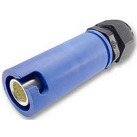
SNLF-S-C25-25S-BL
Description
CONNECTOR, FEMALE, FREE, BLUE
Manufacturer
ITT Cannon
Series
Snaplockr
Datasheet
1.SNLM-P-C25-25S-GY.pdf
(31 pages)
Specifications of SNLF-S-C25-25S-BL
Gender
Receptacle
Voltage Rating
415VAC
Current Rating
250A
Connector Mounting
Cable Mount
Contact Termination
Crimp
Svhc
No SVHC
Connector Type
Standard Power Entry
Cable Diameter Max
14mm
Colour
Blue
Rohs Compliant
Yes
Lead Free Status / RoHS Status
Lead free / RoHS Compliant


www.ittcannon.com/powerlock
Insulated Overhead Line Clamp / Generator Connector
This device allows for direct connection of a generator unit to Low Voltage overhead line systems.
The unit consists of an insulated Line Clamp, 3 metres of 50mm
generator input cable.
The methods of connection is:
1. The copper or alloy overhead wire is cleaned to ensure good connection points.
2. The clamp is hooked onto the wire and tightened via the insulated clamp body.
3. The flexible cable is then strapped to the pole.
4. At the cable end, a POWERLOCK generator connection point is provided for connection of the generator cable.
The generator connection point offers all standard safety features associated with the POWERLOCK range,
such as keys to distinguish phases, IP67 sealing and individual phase color coding.
The insulated T-Piece connector allows the user the option to split one phase into two or combine two phases
into one by the quickest and safest possible means.
The Input and Output connectors are color coded and mechanically keyed the same to prevent connection
errors.
All connectors are IPX2 rated when mated and come with the Secondary Locking as standard.
Position B
Position A
Insulated T-Piece Connector
Insulated Overhead Line Clamp,
Neutral Key Position / Blue
Insulated Overhead Line Clamp
Line 1 Key Position / Brown
Insulated Overhead Line Clamp
Line 2 Key Position / Black
Insulated Overhead Line Clamp
Line 3 Key Position / Grey
Description
Order Information
Position A (x1): Panel Drain Finger Proof (PDFT) or Panel Source (PS)
Position B (x2): Panel Drain Finger Proof (PDFT) or Panel Source (PS)
Phase:
Color:
Amperage:
Version shown: APDFT-BPS-3-BL-T4
24
1, 2, 3, N, E
Red (R), Yellow (Y), Blue (BL), Black (BK), Green (GN)
Brown (BN), Grey (GY), White (W)
400 Amps (T4), 660 Amps (T6)
2
flexible copper cable and a POWERLOCK
Description Code
LVF600-N-BL
LVF600-1-BN
LVF600-2-BK
LVF600-3-GY
ITT Part Number
078214-6303
078214-6300
078214-6301
078214-6302
Related parts for SNLF-S-C25-25S-BL
Image
Part Number
Description
Manufacturer
Datasheet
Request
R

Part Number:
Description:
CONNECTOR, FEMALE, FREE, BLACK
Manufacturer:
ITT Cannon
Datasheet:

Part Number:
Description:
CONNECTOR, FEMALE, FREE, BROWN
Manufacturer:
ITT Cannon
Datasheet:

Part Number:
Description:
CONNECTOR, FEMALE, FREE, GREY
Manufacturer:
ITT Cannon
Datasheet:

Part Number:
Description:
CONNECTOR, FEMALE, FREE, BLUE
Manufacturer:
ITT Cannon
Datasheet:

Part Number:
Description:
CONNECTOR, FEMALE, FREE, GREEN
Manufacturer:
ITT Cannon
Datasheet:

Part Number:
Description:
EMI SHIELDED ENDBELL WITH 4-40 EXTENDED JACKSCREW
Manufacturer:
ITT Cannon
Datasheet:
Part Number:
Description:
UNIVERSAL CONTACT 1.8MM SMD
Manufacturer:
ITT Cannon
Datasheet:
Part Number:
Description:
UNIVERSAL CONTACT 2.5MM SMD
Manufacturer:
ITT Cannon
Datasheet:
Part Number:
Description:
UNIVERSAL CONTACT 3.5MM SMD
Manufacturer:
ITT Cannon
Datasheet:
Part Number:
Description:
PLUG STR CRIMP SMB RG174/U 316/U
Manufacturer:
ITT Cannon
Datasheet:
Part Number:
Description:
TRI TNM RECP M FLG SEAL 0-12
Manufacturer:
ITT Cannon
Datasheet:
Part Number:
Description:
CONN RCPT 6POS JAM NUT W/SCKT
Manufacturer:
ITT Cannon
Datasheet:

Part Number:
Description:
TRI R E/B STR C/C SEAL SZ 18
Manufacturer:
ITT Cannon
Datasheet:
Part Number:
Description:
CAB CON 16S PIN 18/16 F80 SILVER
Manufacturer:
ITT Cannon
Datasheet:

Part Number:
Description:
TRI CON SKT 16-18 TIN ST/LO
Manufacturer:
ITT Cannon
Datasheet: