B50-051-0000220 ITT SEALECTRO, B50-051-0000220 Datasheet - Page 47
B50-051-0000220
Manufacturer Part Number
B50-051-0000220
Description
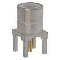
RF/COAXIAL, SMC JACK, STR, 50OHM, SOLDER
Manufacturer
ITT SEALECTRO
Datasheet
1.B50-051-0000220.pdf
(64 pages)
Specifications of B50-051-0000220
Body Style
Straight Jack
Coaxial Termination
Solder
Contact Material
Beryllium Copper
Contact Plating
Gold
Frequency Max
12.4GHz
Connector Type
SMC Coaxial
Impedance
50ohm
Lead Free Status / RoHS Status
Lead free / RoHS Compliant


INSULATOR
Cannon 50 Ohm Connectors
A A I I - - 2 2 5 5 2 2 & & A A I I - - 2 2 7 7 8 8
STEP 5
STEP 1 - 2
STEP 3
STEP 6
www.ittcannon.com
Dimensions shown in mm (inch)
Specifications and dimensions subject to change
CONNECTOR
INSERTING TOOL
DIELECTRIC
PLUG BODY
B
A
INSULATOR
S S M M A A S S t t r r a a i i g g h h t t C C o o n n n n e e c c t t o o r r s s , , D D i i r r e e c c t t S S o o l l d d e e r r
( ( S S e e p p a a r r a a t t e e C C e e n n t t e e r r C C o o n n t t a a c c t t ) ) T T y y p p e e f f o o r r S S e e m m i i - - R R i i g g i i d d C C a a b b l l e e
1.
2.
3.
4.
5.
6.
Assembly Instruction No.
Cut cable end square. Trim the cable outer conductor and dielectric as
shown taking care not to nick the center conductor. Deburr outer conductor at
point of cut.
Tin center conductor (DO NOT OVER TIN).
Solder contact to center conductor ensuring that dimension shown is
maintained. Remove any excess solder.
Clean housing area of outer conductor with abrasive paper and clean in a
suitable agent.
Place connector assembly in Assembly Jig T1848, or other suitable clamping
arrangement, with contact in locator tool as shown.
Tighten screw to secure cable between inserts then tighten locator to seat cable
firmly. Place solder ring around cable adjacent to connector body and heat the
connector body using an appropriate heat source (solder tongs with variable
control). Apply sufficient heat for solder to flow but using minimum heat cycle.
Using dielectric insertion Tool T2508 (for plugs) or T2509 (for jacks), press
insulator into body. Assembly is now ready for use.
N.B. Various body configurations can apply.
CONTACT
AI-252
AI-278
47
JACK BODY
Configuration
Plug
Jack
3,18 +/- 0,25 (.125 +/- .010)
2,54 +/- 0,25 (.100 +/- .010)
ASSEMBLY INSTRUCTIONS
INSULATOR
A
CONTACT
0,38 (.015)
0,38 (.015)
B
Related parts for B50-051-0000220
Image
Part Number
Description
Manufacturer
Datasheet
Request
R

Part Number:
Description:
RF/COAXIAL, SMC PLUG, STR, 50OHM, CLAMP
Manufacturer:
ITT SEALECTRO
Datasheet:

Part Number:
Description:
RF/COAXIAL, SMC PLUG, STR, 50OHM, CRIMP
Manufacturer:
ITT SEALECTRO
Part Number:
Description:
RF/COAXIAL, SMC JACK, STR, 50OHM, CRIMP
Manufacturer:
ITT SEALECTRO
Part Number:
Description:
RF/COAXIAL, SMC JACK, STR, 50OHM, SOLDER
Manufacturer:
ITT SEALECTRO
Part Number:
Description:
RF/COAXIAL, SMB PLUG, STR, 50OHM, CRIMP
Manufacturer:
ITT SEALECTRO