135-3404-001 JOHNSON/EMERSON, 135-3404-001 Datasheet - Page 2
135-3404-001
Manufacturer Part Number
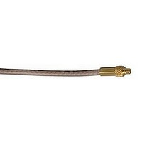
135-3404-001
Description
RF/COAXIAL, MMXC PLUG, STR, 50OHM, CRIMP
Manufacturer
JOHNSON/EMERSON
Datasheet
1.135-3404-001.pdf
(2 pages)
Specifications of 135-3404-001
Body Style
Straight Plug
Coaxial Termination
Crimp
Rg Cable Type
RG-187DS, 188DS, 316DS
Contact Material
Beryllium Copper
Connector Type
MMCX Coaxial
Impedance
50ohm
Lead Free Status / RoHS Status
Lead free / RoHS Compliant


MMCX - 50 Ohm Connectors
Specifications
†Avoid user injury due to misapplication.
See safety advisory definitions inside front cover.
2
ELECTRICAL RATINGS
Impedance: 50 ohms
Frequency Range: Connectors ................................................ 0-6 GHz
VSWR: (f = GHz)
.047 dia flexible .................................... 1.20
RG-178, RG-316, RG-316DS .............. 1.20
.086 semi-rigid ..................................... 1.15
Uncabled receptacles, dummy loads ................................................ N/A
Working Voltage: Connectors ......................... 170 Vrms at sea level†
Dielectric Withstanding Voltage: Connectors...500 Vrms at sea level†
Insulation Resistance: 1000 megohms min
Contact Resistance: (milliohms maximum)
Center contact (straight cabled connectors
Center contact (right angle cabled
Outer contact (all connectors) ..................... 1.0
Braid to body ............................................... 1.5
Corona Level: Connectors ..................... 190 volts min at 70,000 feet†
Insertion Loss: (dB max tested at 1 GHz)
RF Leakage: (dB minimum, tested at 2.5 GHz)
RF High Potential Withstanding Voltage: (400 Vrms at 4 and 7 MHz)†
Power Rating (Dummy Load): - 0.5 watt @ +25 C, derated to 0.25
watt @ +125 C
and uncabled receptacles) ...................... 5.0
connectors) .............................................. 5.0
Straight cabled connectors .............................................................. 0.1
Right angle cabled connectors ........................................................ 0.2
Uncabled receptacles, dummy loads ............................................. N/A
Flexible cable connectors .......................................................... -60 dB
.086 semi-rigid ........................................................................... -70 dB
Dummy loads ................................................................................. N/A
JACK
JACK
Johnson Components
Dummy loads ......................................................... N/A
Dummy loads ............................................ 0-1 GHz
Dummy loads ................................................... N/A
Cabled Connectors
TM
Dummy loads ............................ N/A
Straight
• P.O. Box 1732 • Waseca, MN 56093-0832 • 1-800-247-8256 • Fax: 507-833-6287 • www.johnsoncomponents.com
Initial
Cabled Connectors
Environmental
Right Angle
1.14 + .07f
After
1.25
1.15
15.0
N/A
8.0
1.5
MECHANICAL RATINGS
Engagement Design: Series MMCX
Engagement/Disengagement Force: 8 lbs. max axial engagement
Contact Retention: 2.0 lbs. minimum axial force
Cable Retention:
Connectors for .047 flexible ........................ 3.5
Connectors for RG-178 ............................... 7.0
Connectors for RG-316 .............................. 20.0
Connectors for RG-316DS ......................... 25.0
Connectors for .086 semi-rigid ................... 30.0
*Or cable breaking strength whichever is less.
Durability: .............................................................. 500 cycles minimum
ENVIRONMENTAL RATINGS (Meets or exceed the applicable paragraph
of MIL-C-39012)
Operating Temperature: Connectors ......................... - 65 C to + 165 C
Thermal Shock: Connectors: MIL-STD-202, Method 107, Condition C,
except -55 C to + 155 C (N/A dummy loads)
Corrosion: MIL-STD-202, Method 101, Condition B (N/A dummy loads)
Shock: MIL-STD-202, Method 213, Condition B (N/A dummy loads)
Vibration: MIL-STD-202, Method 204, Condition D (N/A dummy loads)
Moisture Resistance: MIL-STD-202, Method 106 (N/A dummy loads)
MATERIAL SPECIFICATIONS
Bodies: Brass per QQ-B-626, gold plated* per MIL-G-45204 .00001"
Contacts: Beryllium copper per QQ-C-530, gold plated* per MIL-G-
Interface Spring: Beryllium copper per QQ-C-530, gold plated* per
Insulators: PTFE fluorocarbon per ASTM D 1710 and ASTM D 1457
Crimp Sleeves: Copper per WW-T-799 or brass per QQ-B-626, gold
Mounting Hardware: Brass per QQ-B-626 or QQ-B-613, gold plated
PLUG
min.
45204 .00003" min.
MIL-G-45204 .00003" min.
plated per MIL-G-45204 .00001" min.
per MIL-G-45204 .00001" min.
*All gold plated parts include a .00005” min nickel barrier layer.
PLUG
Dummy loads .................... - 65 C to + 125 C
1. ID of contact to meet VSWR mating
2. Must meet the force to engage and dis-
Mating Engagement for MMCX
characteristics and connector durabil-
ity when mated with a dia .016 +/- .001
male contact.
engage when mated with mating part.
CUSTOMER DRAWINGS AVAILABLE UPON REQUEST
Axial Force*
1.4 lbs. min axial disengagement
(pounds)
Series
INCHES (MILLIMETERS)
Torque
(in-oz)
N/A
N/A
N/A
N/A
16
Related parts for 135-3404-001
Image
Part Number
Description
Manufacturer
Datasheet
Request
R

Part Number:
Description:
RF/COAXIAL, MMXC PLUG, R/A, 50OHM, CRIMP
Manufacturer:
JOHNSON/EMERSON
Datasheet:

Part Number:
Description:
CENTER CONTACT HOLDER, SMP CABLED CONN
Manufacturer:
JOHNSON/EMERSON
Datasheet:

Part Number:
Description:
INTERFACE LOCATOR TOOL, SMP CABLED CONN
Manufacturer:
JOHNSON/EMERSON
Datasheet:

Part Number:
Description:
RIGHT ANGLE BODY HOLDER, SMP CABLED CONN
Manufacturer:
JOHNSON/EMERSON
Datasheet:

Part Number:
Description:
FD SHROUD CENTERING TOOL, SMP CABLE CONN
Manufacturer:
JOHNSON/EMERSON
Datasheet: