67.9762-21 MULTI-CONTACT, 67.9762-21 Datasheet - Page 35
67.9762-21
Manufacturer Part Number
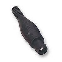
67.9762-21
Description
SOCKET, BNC, RG58/50R, BLACK
Manufacturer
MULTI-CONTACT
Datasheet
1.67.9799-21.pdf
(40 pages)
Specifications of 67.9762-21
Coaxial Termination
Solder / Crimp
Rg Cable Type
RG-58
Contact Material
Brass
Contact Plating
Gold
Frequency Max
3GHz
Connector Mounting
Cable Mount
Connector Type
BNC, Coaxial
Impedance
50ohm
Lead Free Status / RoHS Status
Lead free / RoHS Compliant


Technische Informationen
Durch die kleinere Kapazität bleibt auch der
Einfluss durch die induktiv wirkende Masselei-
tung gering, so dass längere Masseleitungen
verwendet werden können. Bei einem passiven
Tastkopf käme es selbst bei Verwendung kur-
zer Masseleitungen bereits bei einer höheren
Quellimpedanz zu Verzerrungen in der Steilheit
des Pulses bzw. sogar zu rückwirkenden Ein-
flüssen auf das abgetastete Signal.
Ein weiterer Vorteil liegt in der Möglichkeit, mit
einer normierten Ausgangsimpedanz (z. B.
50 W) nicht nur auf Scopes beschränkt arbeiten
zu können. Spätestens hier enden die Einsatz-
möglichkeiten passiver Tastköpfe.
Beispielsweise mit einem Spektrumanalyser
und einem aktiven Tastkopf kann an nahezu al-
len beliebigen Messpunkten einer Schaltung ge-
messen werden. Sicher ist hier zu
berücksichtigen, dass die Dynamik eines Spek-
trumanalysers von über 100 dB, basierend auf
50 W, mit einem aktiven´Tastkopf, basierend auf
einer Impedanz von 1 MW, schon aufgrund der
stärkeren Ankopplung von Störsignalen nicht
erreicht werden kann.
Eine Beurteilung, wo z. B. in einem mehrstufi-
gen Verstärker die Signalbegrenzung eingetre-
ten ist, bewegt sich in einem Pegelbereich
oberhalb von -40 dBm und ist schneller und
leichter möglich.
Ein Nachteil aktiver Tastköpfe ist der begrenzte
Spannungsbereich von max. ±15 V, die maxi-
mal erlaubte Spannung liegt unterhalb von
50 V.
Aktive Tastköpfe bestehen zumeist aus vorge-
schaltetem Spannungsteiler, kapazitätsarmem
FET und weiteren Verstärkerstufen (Impedanz-
wandler). Das macht eine Stromversorgung er-
forderlich.
Technical Information
As a result of the smaller capacity, the inductive
effect of the earth lead remains small so that
longer earth leads can be used. With a passive
test probe, even with short earth leads distor-
tions in the pulse gradient or even retroactive
influences on the test signals would already oc-
cur at a relatively high source impedance.
A further advantage is the possibility, with a
standardised output impedance (e. g. 50 W), of
working with instruments other than oscillosco-
pes. Here, passive test probes already come up
against the limit of their applications.
With a spectrum analyser and an active test
probe, for instance, measurements can be car-
ried out at almost any point in a circuit. Here it
must be borne in mind that the dynamic range
of a spectrum analyser of more than 100 dB,
based on 50 W, cannot be attained with an active
test probe based on an impedance of 1 MW, if
only because of the stronger coupling of interfe-
rence signals.
An assessment, for instance, of where the sig-
nal limitation has occurred in a multi-stage am-
plifier is effected at a level above -40 dBm and
can be carried out more quickly and more easi-
ly.
A drawback of active test probes is the limited
voltage range of ±15 V, the maximum permitted
voltage being less than 50 V.
Active test probes generally consists of voltage
dividers on the input side, low-capacity FETs
and further amplifier stages (impedance con-
verters). As a result, they require a power supp-
ly.
www.multi-contact.com
Informations techniques
Du fait de la capacité plus faible, l’influence
inductive du câble de masse reste faible aussi,
si bien qu’on peut utiliser des câbles de masse
plus longs. Avec une sonde passive, on aurait,
déjà à partir d’une impédance de source plus
élevée, des distorsions dans la raideur de
l’impulsion voire des rétroactions sur le signal
prélevé même en utilisant des câbles de masse
courts.
Un autre avantage réside dans la possibilité,
avec une impédance de sortie normalisée (p. ex.
50 W) de travailler avec d’autres appareils que
l’oscilloscope. On sort ici du cadre d’emploi des
sondes passives.
Avec, par exemple, un analyseur de spectre et
une sonde active on peut mesurer quasiment
tous les points d’un circuit. Certes, il faut tenir
compte du fait que la dynamique d’un analyseur
de spectre de plus de 100 dB, basé 50 W, ne
peut pas être atteinte avec une sonde active,
basée sur une impédance de 1 MW, ne serait-ce
qu’à cause du fort couplage de signaux parasi-
tes.
La détermination de l’endroit où, dans un ampli-
ficateur à plusieurs étages, la limitation de sig-
nal est intervenue, s’effectue dans une plage
de niveau supérieur à -40 dBm et est possible
plus rapidement et plus facilement.
Un inconvénient des sondes actives est la plage
de tension limitée de ±15 V max., la tension
maximale admissible se situant au-dessous de
50 V.
Les sondes actives sont le plus souvent consti-
tuées d’un diviseur de tension placé en amont,
de FET à faible capacité et d’autres étages am-
plificateurs (convertisseur d’impédance). Cela
rend nécessaire une alimentation électrique.
35
®
Related parts for 67.9762-21
Image
Part Number
Description
Manufacturer
Datasheet
Request
R

Part Number:
Description:
SOCKET, BNC, RG58/50R, RED
Manufacturer:
MULTI-CONTACT
Datasheet:

Part Number:
Description:
Metal Film Resistors - Through Hole 1/8watt 67.9Kohms .1% 10ppm
Manufacturer:
Vishay
Part Number:
Description:
Metal Film Resistors - Through Hole 1/8watt 67.9Kohms .1% 10ppm
Manufacturer:
Vishay

Part Number:
Description:
CONN RCPT CONTACT 22-20AWG TIN
Manufacturer:
Tyco Electronics
Datasheet:

Part Number:
Description:
MULTI COAX MICRO MIN SUB-ASSY
Manufacturer:
TE Connectivity
Datasheet:

Part Number:
Description:
CAP, PROTECTIVE, BLACK
Manufacturer:
MC (MULTI CONTACT)
Datasheet:
