2002-6401 WAGO, 2002-6401 Datasheet - Page 59
2002-6401
Manufacturer Part Number
2002-6401
Description
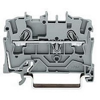
TERMINAL BLOCK, DIN RAIL, 4POS, 22-12AWG
Manufacturer
WAGO
Datasheet
1.2002-6401.pdf
(98 pages)
Specifications of 2002-6401
Connector Type
DIN Terminal Block
Connector Mounting
DIN Rail
No. Of Contacts
4
Wire Size (awg)
22-12
No. Of Positions
1
Terminal Block Clamp Type
Cage Clamp
Current Rating
20A
Color
Gray
Rohs Compliant
Yes
Lead Free Status / RoHS Status
Lead free / RoHS Compliant


* Marks and approval data can be found on the Internet at www.wago.com.
*
U
PCB Terminal Strips 2.5 mm
Pin spacings 5 mm/0.197 in and 7.5 mm/0.295 in; Series 804
Pin spacing 5 mm / 0.197 in
0.5
250 V/4 kV/3; I
500 V/4 kV/2; I
l 10 – 11 mm / 0.41 in
No. of
poles
1-conductor terminal strips with push button,
2 solder pins/pole staggered, grey,
with test slot for test pin Ø 1 mm/0.039 in
10
11
12
13
14
15
16
Pin spacing 10 mm (with spacer) on request
Additional item number for coloured terminal strips
red
blue
orange
light green
Dimensions
2
3
4
5
6
7
8
9
Diameter of drilled hole: 1
L = (No. of poles x pin spacing) + 1.5 mm
<____ 15 ____>
Terminal blocks with blue insulation are suitable for
Ex i applications (only for pin spacing 7.5 mm /
0.295 in and 10 mm /0.394 in)
<___13,5___>
– 2.5 mm
first solder pin
rear side
>
0,6
__> <
5
3,3
<
(in mm)
2
„s+f - st“ AWG 20 – 12 “s+f - st”
N
N
___>
1,25
Item
No.
804-102
804-103
804-104
804-105
804-106
804-107
804-108
804-109
804-110
804-111
804-112
804-113
804-114
804-115
804-116
. . . /000-005
. . . /000-006
. . . /000-012
. . . /000-017
16 A 300 V, 10 A U
16 A
2,5
__>
<_____________L_____________>
<
+0. 1
<
mm
0,8
__> <
Pack. unit
pcs
420 (4 x 10⁵)
280 (4 x 70)
220 (4 x 55)
180 (4 x 45)
140 (4 x 35)
120 (4 x 30)
100 (4 x 25)
100 (4 x 25)
80 (4 x 20)
80 (4 x 20)
60 (4 x 15)
60 (4 x 15)
60 (4 x 15)
60 (4 x 15)
40 (4 x 10)
( 5 )
*
U
Pin spacing 7.5 mm / 0.295 in
0.5
400 V/6 kV/3; I
800 V/6 kV/2; I
l 10 – 11 mm / 0.41 in
No. of
poles
1-conductor terminal strips with push button,
2 solder pins/pole staggered, grey,
with test slot for test pin Ø 1 mm/0.039 in
10
11
12
Ordering example
Terminal strip, pin spacing 5 mm /0.197 in, 8 poles,
orange
2
2
3
4
5
6
7
8
9
/AWG 14
Diameter of drilled hole: 1
L = (No. of poles – 1) x pin spacing + 5 mm + 1.5 mm
<____ 15 ____>
<___13,5___>
– 2.5 mm
first solder pin
rear side
>
0,6
__> <
5
3,3
<
2
„s+f - st“ AWG 20 – 12 “s+f - st”
N
N
1,25
___>
Item
No.
804-302
804-303
804-304
804-305
804-306
804-307
804-308
804-309
804-310
804-311
804-312
804-108/000-012
16 A 300 V, 10 A U
16 A
__>
2,5
<_____________L___________>
57
<
+0. 1
<
mm
0,8
__> <
(_7,5 _)
Pack. unit
pcs
320 (4 x 85)
220 (4 x 55)
160 (4 x 40)
120 (4 x 30)
100 (4 x 25)
80 (4 x 20)
80 (4 x 20)
60 (4 x 15)
60 (4 x 15)
60 (4 x 15)
40 (4 x 10)
5
<
Accessoires
Internal commoning
Marker cards,
Print - Pin spacing 5 mm /0.197 in
13–24 (300 x)
Print - Pin spacing 7.5 mm /0.295 in
Direct printing on request
Test pin, Ø 1 mm/0.039 in
Screwdriver with partially insulated shaft,
Internal commoning
For example, the requirement of not routing the
ground (earth) conductors over the board is met
by WAGO through the “internal commoning” of
804 Series terminal strips. This way, custom termi-
nal strips can be commoned to each other and
marked at the factory.
1–12 (300 x)
1–16 (100 x)
°
Item
No.
100 self-adhesive
strips per card
210-331/0500-0103 1 card
210-331/0500-0104 1 card
210-331/0750-0202 1 card
735-500
Test wire for sold. onto test plug
3.5 x 0.4 mm /0.137 in x 0.016 in
210-620
Pack. unit
pcs
1
1
1
Related parts for 2002-6401
Image
Part Number
Description
Manufacturer
Datasheet
Request
R


Part Number:
Description:
TERMINAL BLOCK, DIN RAIL, 6POS, 22-12AWG
Manufacturer:
WAGO

Part Number:
Description:
HOLDER BATTERY 4CELL D ALUMINUM
Manufacturer:
Keystone Electronics
Datasheet:


Part Number:
Description:
4 CHAN DIG INPUT 5VDC .2mS
Manufacturer:
WAGO
Datasheet:

Part Number:
Description:
Series 200 Switches Toggle Switches - Sub Miniature
Manufacturer:
e-switch
Datasheet: